Dual stage actuator suspension having a single microactuator and employing pseudo symmetry to achieve suspension balance

a microactuator and suspension technology, applied in the direction of maintaining head carrier alignment, recording information storage, instruments, etc., can solve the problem that dsa suspensions have only been available recently in the commercial mark

Active Publication Date: 2012-07-24
MAGNECOMP
View PDF20 Cites 55 Cited by
  • Summary
  • Abstract
  • Description
  • Claims
  • Application Information

AI Technical Summary

Benefits of technology

[0012]The present invention is of a DSA type suspension requiring only a single non-split PZT microactuator, but which nevertheless is balanced about the central longitudinal axis of the suspension or load beam to within an acceptably high degree of mass balance and inertial balance. A mechanically balanced suspension will generally perform better, such as by not twisting in response to vertical movements of the suspension as the disk surface flutters or as the drive is bumped.

Problems solved by technology

Due to the additional cost of DSA suspensions over traditional suspensions, it is believed that DSA suspensions have only been recently become available commercially.

Method used


Image

  • Dual stage actuator suspension having a single microactuator and employing pseudo symmetry to achieve suspension balance
  • Dual stage actuator suspension having a single microactuator and employing pseudo symmetry to achieve suspension balance
  • Dual stage actuator suspension having a single microactuator and employing pseudo symmetry to achieve suspension balance

Examples


first embodiment

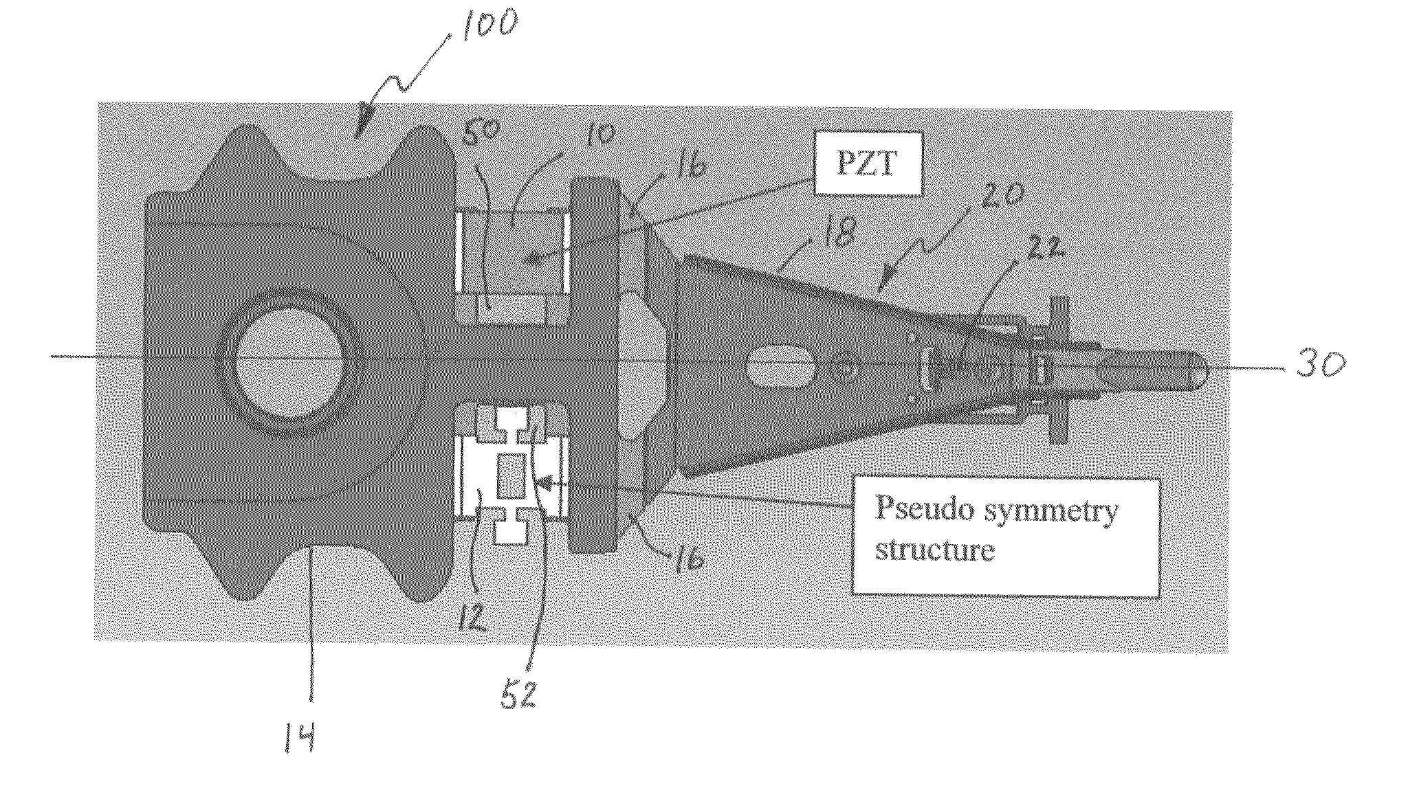
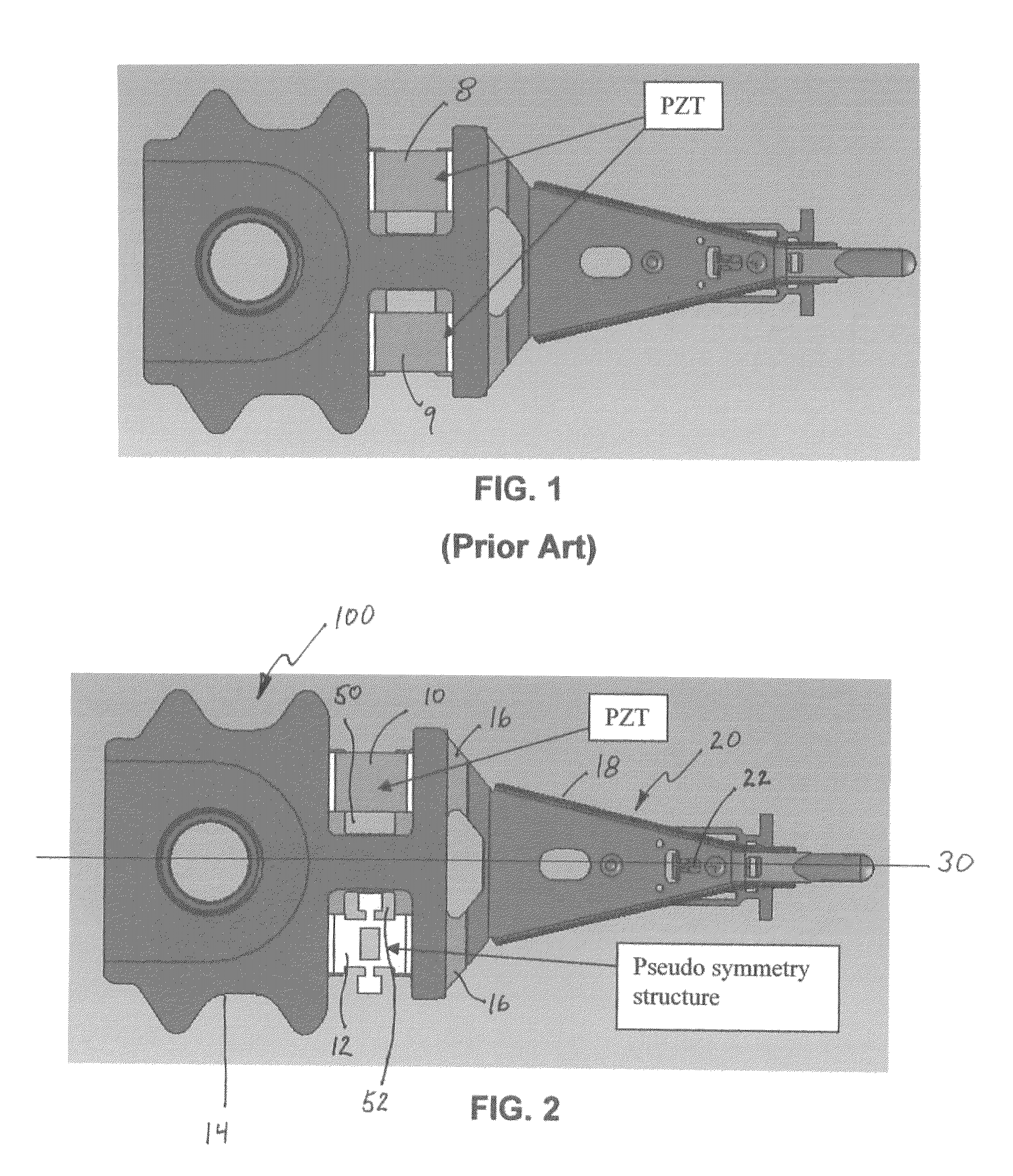
[0025]FIG. 2 is a top plan view of a DSA suspension 100 having PZT 10 and balancing structure or pseudo symmetry structure 12 according to the present invention. PZT 10 has convention electrical connections thereto (not shown) that will add somewhat to the weight and inertial characteristics of PZT 10. For purposes of the present discussion throughout this disclosure and the appended claims, what will be referred to as the PZT or other microactuator encompasses the electrical connections thereto and their weights. Pseudo symmetry structure 12 may be fabricated separately and thereafter affixed to suspension 100 such as by an adhesive such as epoxy, or by laser welding. It is currently anticipated that the preferred embodiment will include at least one added stainless steel component that is formed separately and later affixed to the suspension by welding. Accordingly, in the discussion that follows, although the pseudo symmetry structure component will be referred to for brevity as ...

second embodiment

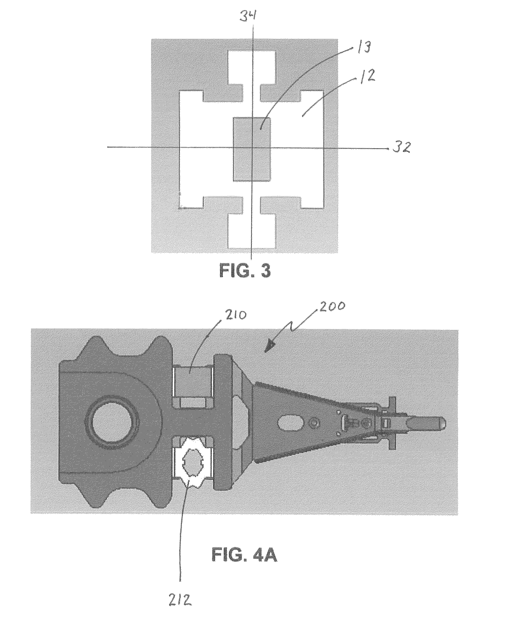
[0030]FIG. 4A is a top plan view of a DSA suspension 200 having a single non-split PZT 210 and a pseudo symmetry structure 212 according to the invention. This embodiment is similar to the embodiment of FIG. 2 except that the shape of pseudo symmetry structure 212 is different.

[0031]FIG. 4B is a bottom plan view of the suspension of FIG. 4A. This view shows magnetic head slider 260 which is a conventional head slider. In operation, PZT microactuator 210 expands or contracts in response to a microactuator driving voltage applied thereto causing the distal end of suspension 200 carrying head slider 260 to move slightly up or down as oriented in the figure, thus effecting microfine movements of head slider 260 in order to keep head slider 260 properly positioned over the desired data track on the magnetic disk surface (not shown). Pseudo symmetry element 212 counterbalances PZT both statically and inertially.

[0032]FIG. 5 is a top plan view of the pseudo symmetry structure 212 of the su...


PUM

PropertyMeasurementUnit
massaaaaaaaaaa
stiffnessaaaaaaaaaa
pseudo symmetry structureaaaaaaaaaa

Abstract

A dual stage actuator (DSA) suspension has a single microactuator such as a PZT element on one side of central longitudinal axis of the suspension, and a pseudo symmetry structure formed or affixed on the other side of the central longitudinal axis opposite the PZT. The pseudo symmetry structure has mass and stiffness that mirrors the PZT, thus keeping the suspension mechanically balanced and symmetric about the longitudinal axis for improved suspension performance especially in a shock environment.

Description

CROSS-REFERENCE TO RELATED APPLICATIONS[0001]This application claims priority from U.S. Provisional Patent Application Ser. No. 61 / 152,865 filed Feb. 16, 2009, the disclosure of which is incorporated by reference herein as if set forth in its entirety.BACKGROUND OF THE INVENTION[0002]1. Field of the Invention[0003]This invention relates to the field of hard disk drive suspensions having dual stage actuators. More particularly, this invention relates to the field of a dual stage actuator suspension for a hard disk drive, the suspension having a single microactuator device and employing pseudo symmetry to balance the suspension.[0004]2. Description of Related Art[0005]In a hard disk drive, the suspension is the component that holds the read-write head over the desired data track on the spinning magnetic hard drive. The disk drive could also be an optical disk or possibly other data storage technologies. As track densities increase and drives are made smaller, there is a constant need ...

Claims


Application Information

Patent Timeline
Patent Type & Authority Patents(United States)
IPC IPC(8): G11B21/24G11B5/596
CPCG11B5/4873Y10T29/49025
Inventor HAHN, PETERCHAI, WEI KEATEE, KUEN CHEE
Owner MAGNECOMP
Why Eureka
Try Eureka