
Multi chip electronic system

a technology of electronic systems and chips, applied in the field of electronic systems, can solve the problems of high development cost, complex manufacturing process, and substantial impact on the total production cost of the implemented electronic system, and achieve the effect of saving area, avoiding the necessity of duplicating circuit structures, and cost amortization

Active Publication Date: 2012-07-24
STMICROELECTRONICS SRL
View PDF2 Cites 142 Cited by
  • Summary
  • Abstract
  • Description
  • Claims
  • Application Information

AI Technical Summary

Benefits of technology

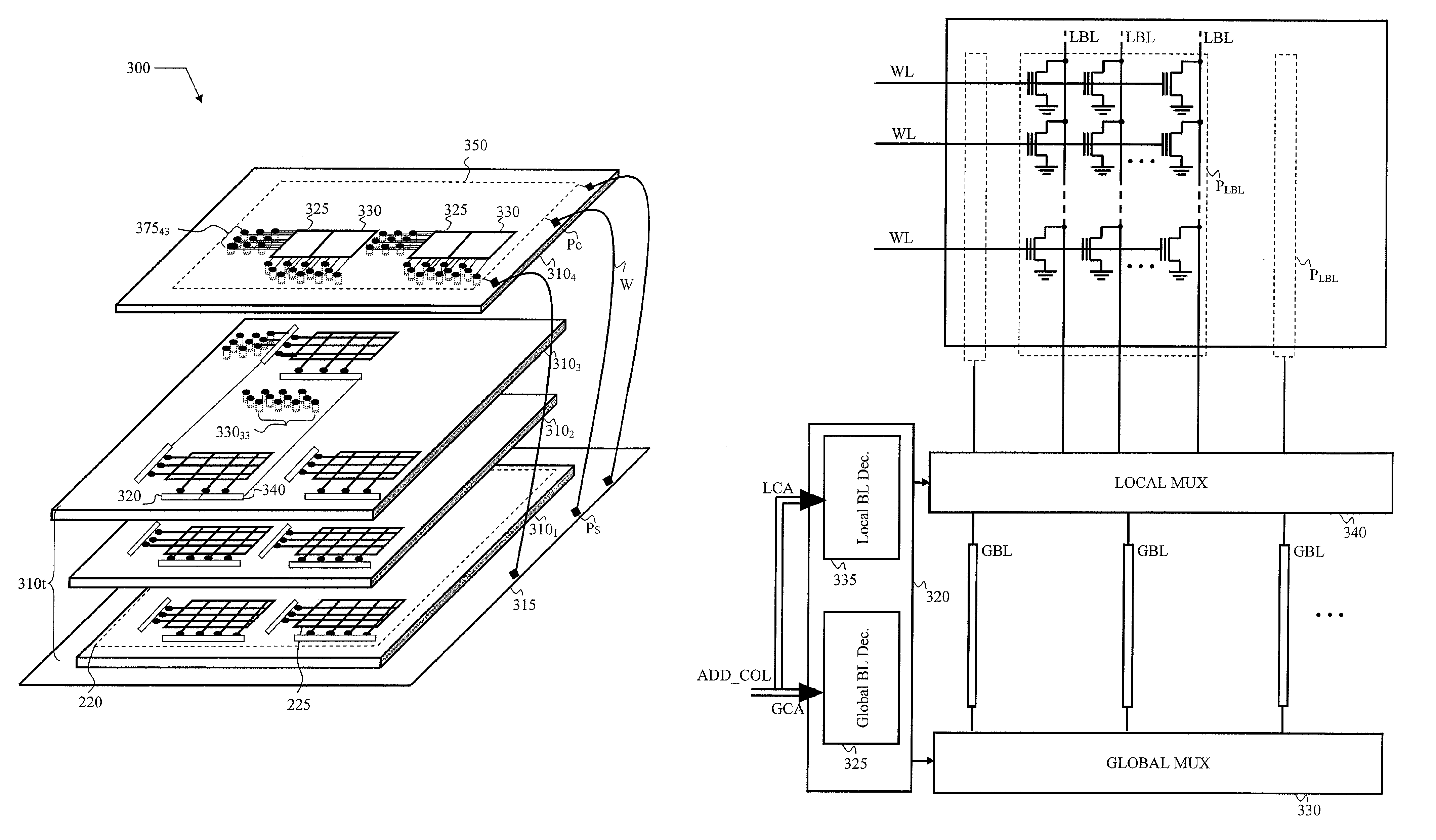
[0016]In this way, not only it is possible to save area, inasmuch the necessity of duplicating circuit structures is avoided, or however it is reduced, but it is also possible to exploit to the best the lithographic apparatuses; in fact, the most sophisticated and expensive apparatuses can mostly be devoted to the integration of the sub-systems designed with more stringent rules, such as for instance the memory matrices, while for the realization of the ICs devoted to service circuit structures, that are designed with more relaxed rules, apparatuses of preceding generations can be employed, whose cost has already been amortized.

Problems solved by technology

The complexity of the manufacturing process constitutes a disadvantage of the SOCs, that has a significant impact in terms of achievable yield in manufacturing process.
Additionally, the SOCs of “full custom” type exhibit a high cost of development, which substantially impacts on the total production costs of the implemented electronic system.
The Applicant has observed that the integration, on every chip, of the service circuit structures, is disadvantageous in general, since it leads to an increase in area of material, and this is particularly true in systems to be used in portable apparatuses (like, for instance, in MP3 devices and in cellular phones), in which it is important to reduce the space occupation.

Method used


Image

  • Multi chip electronic system
  • Multi chip electronic system
  • Multi chip electronic system

Examples


Embodiment Construction

[0027]In the following description, similar or identical elements in the drawings are denoted with the same references numerals.

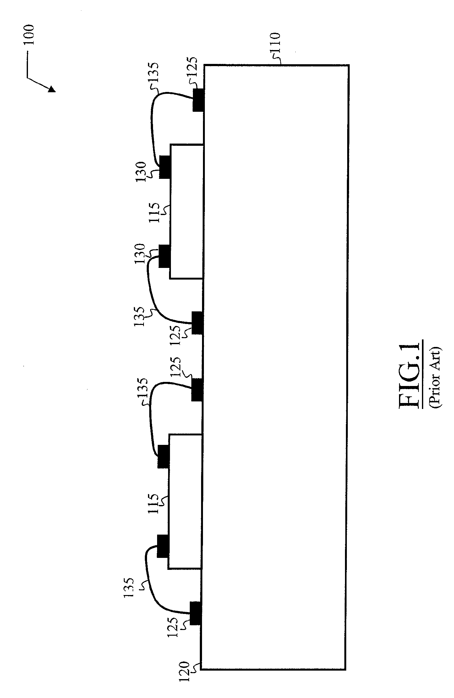
[0028]With reference to FIG. 1, a conventional SIP 100 is shown. The SIP 100 includes a chip support or “chip carrier”110, two (as in the example) or more chips 115, that are placed on the upper surface 120 of the support 115; an encapsulation layer (not shown in the figure) covers two (or more) chips 115, encapsulating them. The support 110 includes a plurality of contact pads 125. The chips 115 also include a plurality of contact pads 130, that are electrically connected to the contact pads 125 of the support 110 through conductive wires 135.

[0029]Every chip 115 integrates a respective IC that in use is adapted to perform its own function, thus implementing different sub-systems of the overall electronic system.

[0030]To this purpose, every IC integrated in one of the chips 115 includes a functional circuit core, adapted to implement the functionality requ...


PUM


Abstract

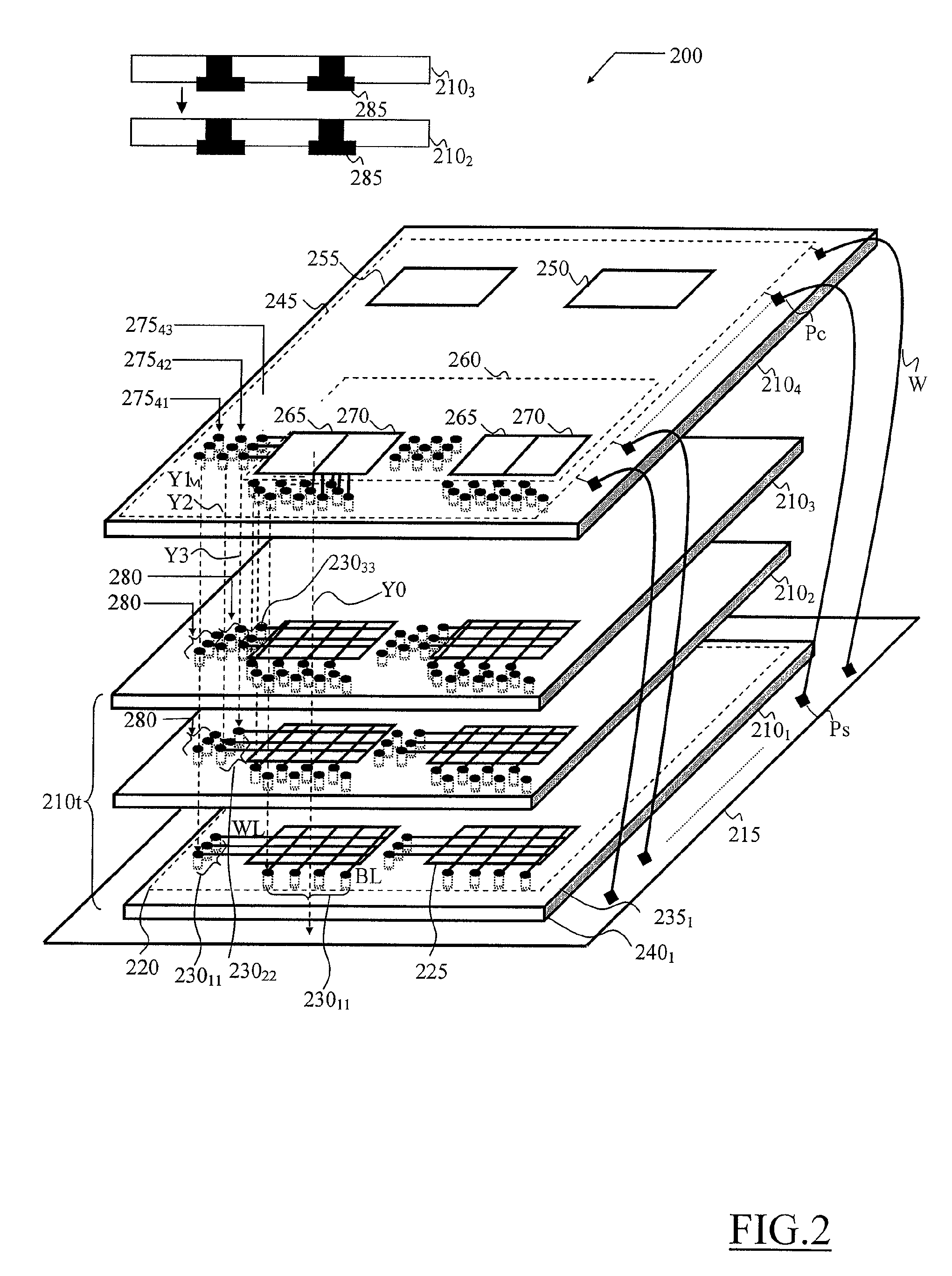
An electronic system adapted to perform a corresponding function and including at least a first subsystem and a second subsystem, the first subsystem and the second subsystem being operatively couplable to each other through a plurality of electric connections to perform the function of the system, in which the first subsystem and the second subsystem are respectively integrated on a first material chip and on a second material chip, the plurality of electric connections including a plurality of conductive through holes formed in at least one of the first and second chips and adapted to form a corresponding plurality of inter-chip electric connections when the first and the second chips are superimposed.

Description

BACKGROUND OF THE INVENTION[0001]1. Field of the Invention[0002]The present invention concerns electronic systems in general, and particularly electronic systems realized in the form of Integrated Circuits (“IC”), integrated in two or more chips.[0003]2. Discussion of the Related Art[0004]“Multi-Chip Modules” or MCM, also known as SIP (“System-in-Package”, i.e. electronic systems contained in a single package) are known in the art, that include two or more ICs, constituting respective sub-systems of the electronic system, integrated in respective chips and contained in a single package.[0005]The SIPs are often used in alternative to systems denominated SOCs, (“System-On-Chip”, i.e. whole electronic systems integrated on a single chip), in which all the circuital parts that compose of the electronic system to be realized are integrated in a single chip.[0006]In an SOC, the IC integrated in the single chip can for instance include a microcontroller or a microprocessor, and / or a Digita...

Claims


Application Information

Patent Timeline
Patent Type & Authority Patents(United States)
IPC IPC(8): H05K1/11H05K1/14
CPCH01L25/0657H01L2224/48091H01L2224/48227H01L2225/0651H01L2924/01019H01L2225/06517H01L2225/06596H01L2924/1461H01L2924/13091H01L2225/06513H01L2924/00014H01L2924/00
Inventor LOSAVIO, ALDOCAMPARDO, GIOVANNIRICCIARDI, STEFANO
Owner STMICROELECTRONICS SRL
Learn More