Functionalized monolayers for carbon dioxide detection by a resonant nanosensor

a nanosensor and carbon dioxide technology, applied in the field of sensing devices and techniques, can solve the problems of low cost of fabricating such sensors for large area cosub>2 /sub>monitoring, poor drift behavior, and lack of long-term performance stability, so as to facilitate understanding

Active Publication Date: 2012-07-31
HONEYWELL ROMANIA
View PDF10 Cites 8 Cited by
  • Summary
  • Abstract
  • Description
  • Claims
  • Application Information

AI Technical Summary

Benefits of technology

[0013]The sensing monolayer can also be configured by bridging the carbon atoms with respect to the vibrating beams. The wafer containing the hydrogen-terminated surface may be immersed in a sealed flask containing a mixture of unprotected amine (e.g., 3 butenyl-amine-Cbz; and N-methyl-3butenylamine-Cbz) and heated in toluene in order to form the sensing monolayer connected to the wafer surface by the carbon atoms. The reference monolayer containing only non-sensing protonated terminal groups may be obtained from the sensing monolayer by exposing the reference beam to liquid HCl by a direct printing process on the reference beam. The disclosed differential resonant nanosensor apparatus containing sensing and reference layers can therefore provide a genuine all-differential gas sensing application.

Problems solved by technology

Unfortunately, the cost for fabricating such sensors for large area CO2 monitoring is high.
Problems associated with prior art resonant sensors, and which may propagate to emerging resonant nanosensor devices, include a lack of long term performance stability and a poor drift behavior due to poor baseline stability (i.e., recovery of the sensor signal to the same response level in the absence of the gas to be detected).
Other problems include its inherent temperature variations and temperature dependence of the resonance frequency, the fatigue of the vibrating beam, humidity absorption, and aging of its sensing layer, which may exhibit or contribute to a baseline drift.

Method used


Image

  • Functionalized monolayers for carbon dioxide detection by a resonant nanosensor
  • Functionalized monolayers for carbon dioxide detection by a resonant nanosensor
  • Functionalized monolayers for carbon dioxide detection by a resonant nanosensor

Examples


Embodiment Construction

[0023]The particular values and configurations discussed in these non-limiting examples can be varied and are cited merely to illustrate one or more embodiments and are not intended to limit the scope thereof.

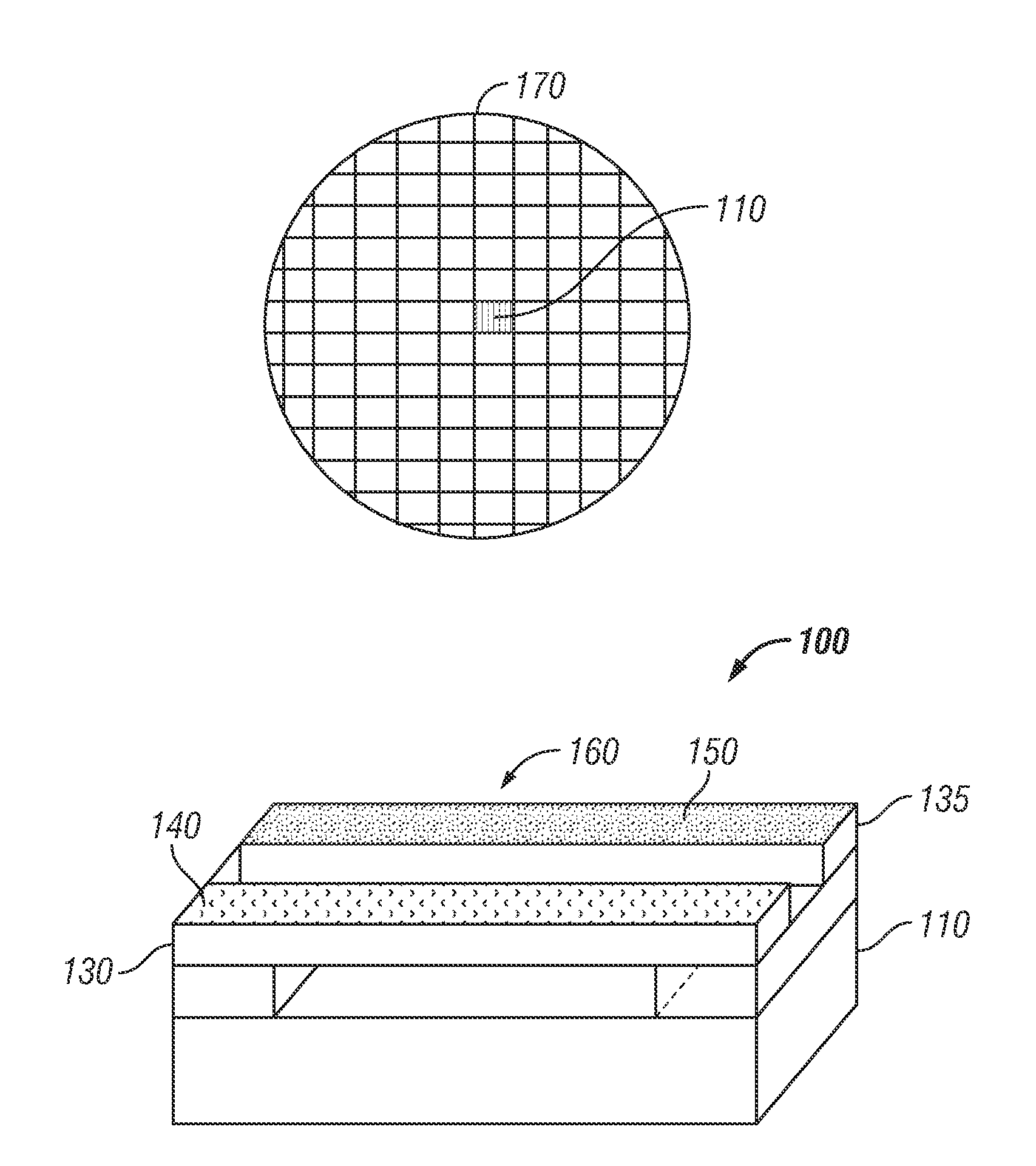
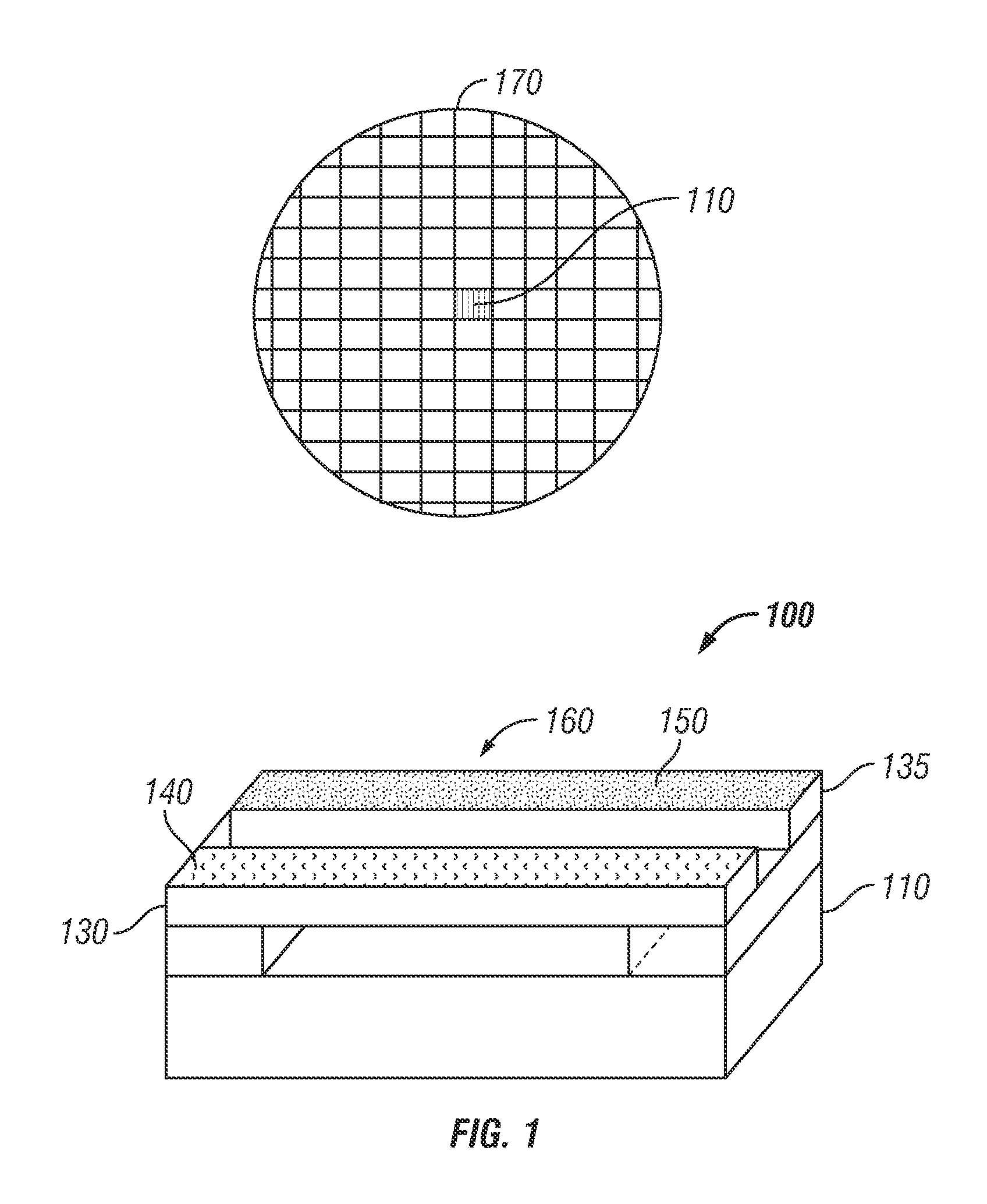
[0024]FIG. 1 illustrates a perspective view of an exemplary resonant nanosensor apparatus 100 and a schematic view of a processed silicon wafer containing a multitude of resonant nanosensor(s) 100, in accordance with the disclosed embodiments. Note that in FIGS. 1-16, identical or similar blocks are generally indicated by identical reference numerals. The resonant nanosensor apparatus 100 with gas detection capability may be employed to detect a gas (e.g. carbon dioxide) by eliminating base line drift issues. The apparatus 100 generally includes a sensing resonant beam 130 and a reference resonant beam 135 located on a chip 110, included in the wafer 170, which contains a multitude of such chips 110. The sensing beam 130 further includes a sensing monolayer 140 and the referenc...


PUM

PropertyMeasurementUnit
visco-elastic propertiesaaaaaaaaaa
concentrationaaaaaaaaaa
electrochemicalaaaaaaaaaa

Abstract

A resonant nanosensor apparatus associated with a functionalized monolayer for detecting carbon dioxide and a method of forming the same. A wafer including a sensing vibrating beam and a reference vibrating beam may be functionalized with a functional group in order to form a sensing self monolayer. The sensing self assembled monolayer may be configured by bridging oxygen or carbon atoms covalently bonded with respect to the vibrating beams. A liquid solution of hydrochloric acid may then be applied to the sensing self assembled monolayer at the surface of the reference beam by a direct printing process to obtain a reference monolayer. The liquid solution of HCl transforms the functional groups responsible for the carbon dioxide detection into protonated groups, which do not react with carbon dioxide, but possess visco-elastic properties similar to that of the sensing monolayer.

Description

CROSS-REFERENCE TO PROVISIONAL APPLICATION[0001]This application claims priority under 35 U.S.C. §119(e) to U.S. Provisional Application Ser. No. 61 / 262,702, entitled “Functionalized Monolayers for Carbon Dioxide Detection by a Resonant Nanosensor,” filed on Nov. 19, 2009, the entire disclosure of which is hereby incorporated by reference for all purposes as if fully set forth herein.TECHNICAL FIELD[0002]Embodiments are generally related to sensing devices and techniques. Embodiments are also related to nano-electromechanical systems (NEMS) for gas sensing applications. Embodiments are additionally related to functionalized monolayers and nano-resonators.BACKGROUND OF THE INVENTION[0003]As the demand for energy resources increases simultaneously with the decrease in available fossil fuels, various alternative sources of energy such as coal-based energy technologies, for example, are being deployed. Large amounts of CO2 are generated by coal gasification processes in power plants, fo...

Claims


Application Information

Patent Timeline
Patent Type & Authority Patents(United States)
IPC IPC(8): G01N29/02G01N7/00G01N21/00G01N31/00G01N33/00G01N30/96G01N27/00
CPCG01N29/022G01N29/036G01N29/30G01N33/004G01N2291/021G01N2291/0255G01N2291/0256G01N2291/0427G01N2610/00
Inventor SERBAN, BOGDAN-CATALINCOBIANU, CORNELMIHAILA, MIHAI N.DUMITRU, VIOREL-GEORGEL
Owner HONEYWELL ROMANIA
Why Eureka
Try Eureka