
Internal combustion engine

a combustion engine and combustion chamber technology, applied in the field of motor engineering, can solve the problems of affecting engine operating stability, leaner mixture in fuel over the permissible limit, and more lean mixture in combustion chamber, so as to improve the quality of the fuel-air mixture, improve the mixing effect of fuel, and increase the gasification time

Inactive Publication Date: 2012-08-07
SERGEEV ALEXANDR NIKOLAEVICH
View PDF15 Cites 0 Cited by
  • Summary
  • Abstract
  • Description
  • Claims
  • Application Information

AI Technical Summary

Benefits of technology

[0011]The proposed engine design and the means for control ensure achievement of the technical result, since they eliminate the drawbacks of the prototype. This is ensured by the fact that the change in the pre-ignition chamber shape, angling the channels for fuel-air mixture delivery into the combustion chamber towards each other and suggested limiting of the angle between the axes of these channels and the axis of the combustion chamber, shall ensure more even distribution of the fuel-air mixture within the volume of the pre-ignition chamber and the combustion chamber. The presence of the return valve between the fuel delivery channel and the compressor cylinder will prevent the backflow of the fuel-air mixture through the injection nozzle and eliminate the need to use expensive high pressure equipment. Tangential connection of the fuel delivery channel with the air supply channel in the direction aligned along the air flow will ensure better mixing of fuel with air, thus making the fuel-air mixture more homogeneous. Locating the fuel delivery device in the bottom part of the compressor cylinder will allow for fuel delivery at the beginning of the movement of the compressor piston from the lower dead point towards the upper dead point. This will increase fuel gasification time by 50%. In this case gasification will occur during the time when the engine crankshaft turns by 540°. This will improve the quality of the fuel-air mixture, leading to more complete burning of the fuel in the combustion chamber, reducing the toxicity of the exhaust gases and increasing engine power. Using two fuel delivery devices in the proposed engine, with one device located in the bottom part of the compressor cylinder and connected with the air supply channel, and the second one located in the top part of the compressor cylinder above the upper dead point of the compressor piston, will make it possible to reduce the fuel injection time by half, thus correspondingly increasing the time of fuel gasification, and also will improve conditioning of the fuel-air mixture.
[0012]The presence of the throttle plate in the channel for air delivery into the compressor cylinder and air mass flow meter connected with it linked to the controller that controls the fuel delivery device, will make it possible to maintain the set fuel and air ratio in the fuel-air mixture within the compressor cylinder, thus ensuring stable operation of the engine in all modes. Initiating fuel delivery into the air supply channel at the time of the beginning of the movement of the compressor piston from the lower dead point to the upper dead point will increase fuel gasification time by 50%; this will also contribute to forming a more homogeneous fuel-air mixture. As a result, engine operating stability improves and fuel usage rate decreases.

Problems solved by technology

However, when the engine operates according to the prototype the fuel-air mixture, passing along the channels from the compressor gun to the pre-ignition chamber and combustion chamber, may cool down, which will lead to the formation of the liquid drop phase in the fuel-air mixture composition, making the mixture leaner in fuel in excess of the permissible limit.
In addition to that, part of the fuel-air mixture, sliding along the combustion chamber walls under the influence of the vertical component of centrifugal forces, may untimely (prematurely) be thrown out to the above (over)-piston space, making the mixture that remains in the combustion chamber more lean.
As a result the engine operating stability will be impacted, its power will be reduced and fuel consumption rate will increase.
However, tests of the prototype engine showed that the jet of the fuel-air mixture after entering the pre-ignition chamber and combustion chamber clings to the chamber walls; by eddying it creates a stagnation pocket in the middle of the said chambers.
The pocket is not engaged in the mixing process, thus resulting in a mixture of uneven quality.
Besides, during compression of the fuel-air mixture in the compressor cylinder pressure may exceed the level for which the fuel inlet device is rated (for example, the nozzle).
This may lead to a fuel supply interruption resulting in power reduction and unstable operation of the engine.
Utilizing high pressure nozzles and pump will significantly increase the cost of the engine.
This time may not be sufficient for full gasification of the fuel; that would also result in negatively impacting operating stability of the engine, increasing inefficient fuel consumption and increasing pollution of the environment.

Method used


Image

  • Internal combustion engine
  • Internal combustion engine
  • Internal combustion engine

Examples


Embodiment Construction

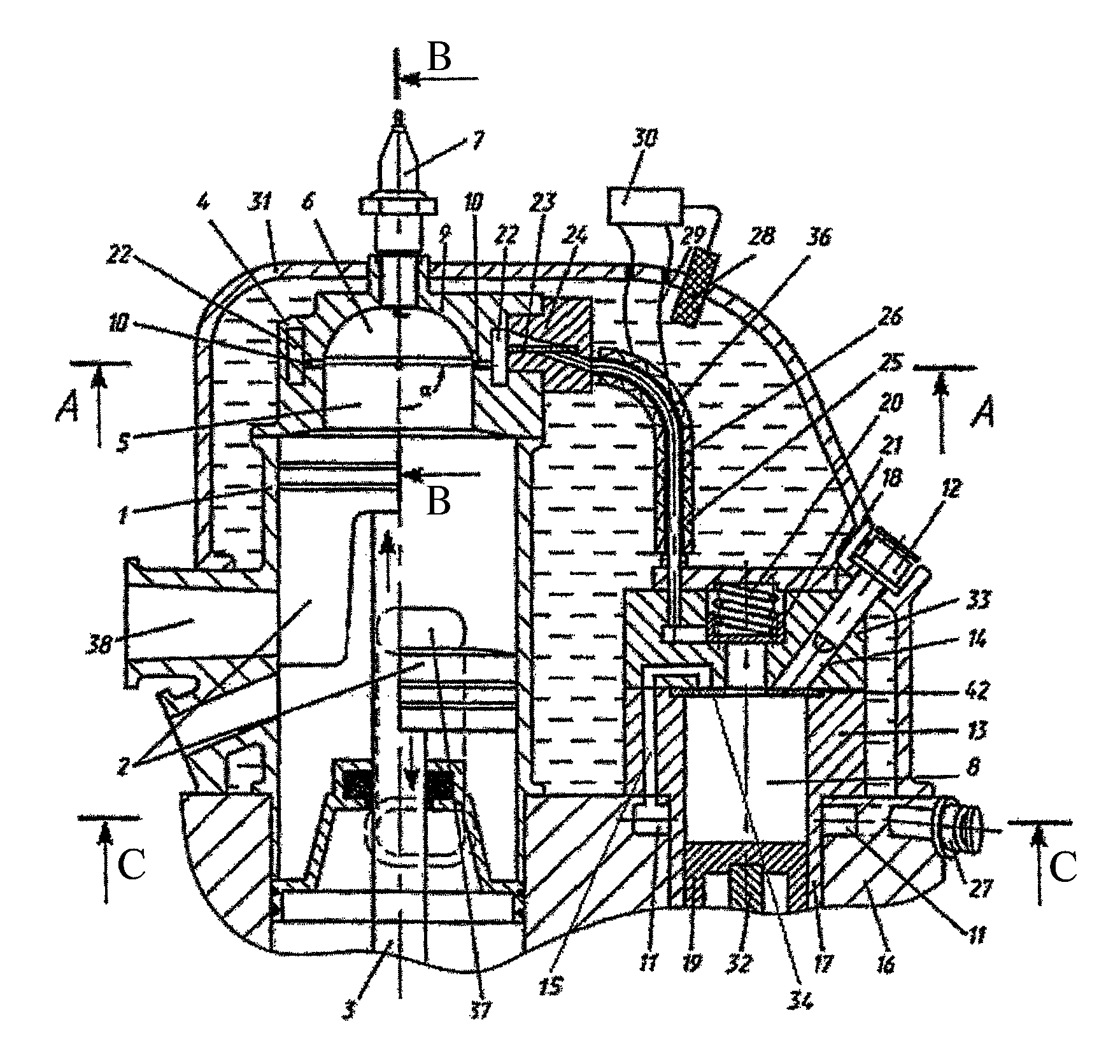
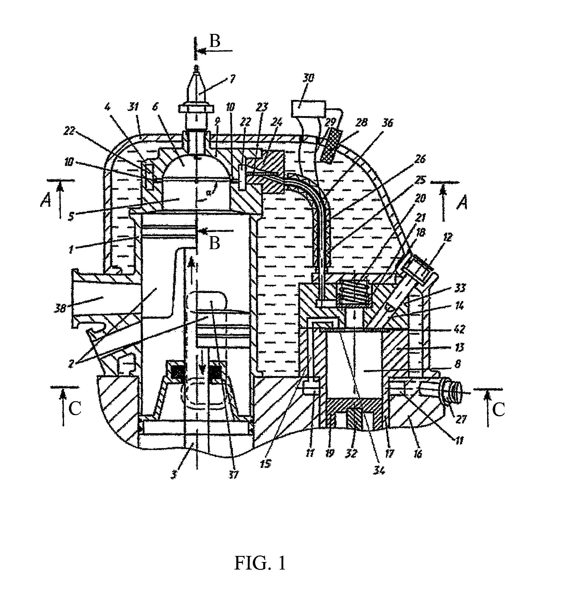
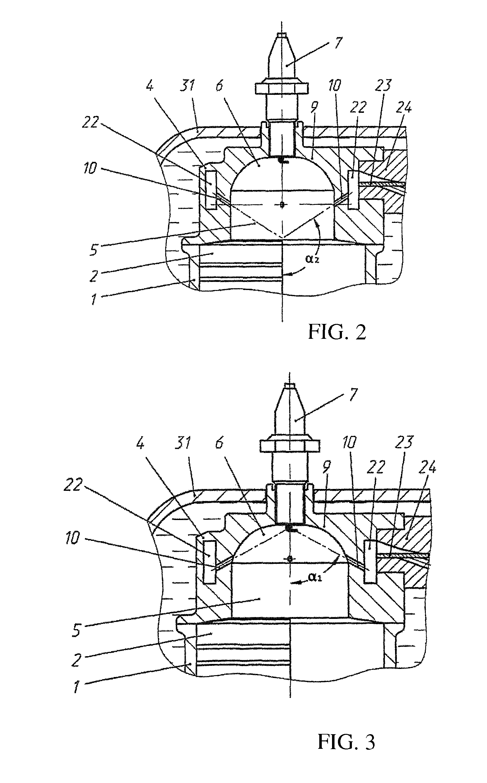
[0019]The proposed internal combustion engine contains a working cylinder 1 with a piston 2, connected to a rod 3. In the working cylinder 1 openings 37 and 38 are provided for air intake and exhaust discharge. In the head 4 of the working cylinder 1, the combustion chamber 5 and pre-ignition chamber 6 with spark plug 7 are located. The combustion chamber 5 is cylindrical in shape and the pre-ignition chamber 6 has a cup-like shape as shown on FIG. 1, or is in the shape of a truncated cone. The diameter of the base of the pre-ignition chamber 6 is equal to the diameter of the combustion chamber 5. The engine is equipped with a fuel-air mixture gun, which is the compressor cylinder 13, which consists of a case 17 and cover 33. The cavity 8 of the compressor cylinder 13 is connected with the combustion chamber via a cutoff valve 21 with spring 20, which is retained by a plate 18, a fuel-air mixture delivery channel 36, which is represented by pipe 26, fitted with a heater 25; return v...


PUM


Abstract

The invented engine comprises a working cylinder with a piston, pre-ignition chamber with spark plug and a combustion chamber which is cylindrical in shape, a fuel-air mixture injector, which is a compressor cylinder with a piston and fuel delivery device and channels for supplying the fuel and air into the combustion chamber. It also has channels for injection of the fuel-air mixture into the combustion chamber. There is a check valve between the fuel supply channel and the compressor cylinder. The pre-ignition chamber has the shape of a cup or flattened cone. The diameter of the base of the pre-ignition chamber equals the diameter of the combustion chamber. The engine has one or more pairs of channels for delivering the fuel-air mixture to the combustion chamber. The axes of these channels are paired and angled towards each other. The angle between the axes of these channels and the axis of the combustion chamber is selected within the interval between the crossing point of the axes of these channels on the central electrode of the ignition plug and the crossing point of the axis of the combustion chamber with the bottom of the working piston in its top dead point position. The invention provides for improving operation stability of the engine, reducing fuel consumption rate and reducing the toxicity of the exhaust gases by increasing homogeneity of the fuel-air mixture.

Description

RELATED APPLICATIONS[0001]This application is a Continuation of PCT application serial number PCT / RU2008 / 000694 filed on Nov. 7, 2008 which in turn claims priority to Russian application number RU2007149349 filed Dec. 29, 2007, both of which are incorporated herein for reference in their entirety.FIELD OF THE INVENTION[0002]The invention relates to motor engineering and can be implemented when manufacturing and operating internal combustion engines with an injection system of fuel-air mixture into the working cylinder of the engine.BACKGROUND OF THE INVENTION[0003]The internal combustion engine is known (RU Patent No. 2230202C1, dated 8 Jan. 2003, International Patent Classification 7 F02B19 / 10). This engine comprises a working cylinder provided with a piston, a fuel-air mixture compressor gun and a cylinder head, where a spherical or conical combustion chamber is placed along with a cylindrical pre-ignition chamber. The combustion chamber and the pre-ignition chamber are connected ...

Claims


Application Information

Patent Timeline
Patent Type & Authority Patents(United States)
IPC IPC(8): F02B19/16F02B33/22
CPCF02B19/06Y02T10/125Y02T10/12
Inventor SERGEEV, ALEXANDR NIKOLAEVICH
Owner SERGEEV ALEXANDR NIKOLAEVICH
Learn More