Piston ring

a technology of piston rings and rings, applied in the field of piston rings, can solve problems such as increasing difficulty in obtaining the required parts

Active Publication Date: 2012-08-07
FEDERAL MOGUL BURSCHEID
View PDF18 Cites 9 Cited by
  • Summary
  • Abstract
  • Description
  • Claims
  • Application Information

AI Technical Summary

Benefits of technology

[0007]The task underlying the invention is to develop the state of the art further, to the effect that while retaining a lower edge on the piston ring with the sharpest edge possible a contact surface coating of reduced coating thickness may be applied, in order to guarantee an increased break-out safety in this area.

Problems solved by technology

In the case of coated piston rings these requirements prove to be increasingly difficult, dependent upon the coating thickness of the contact surface layer.

Method used


Image

  • Piston ring
  • Piston ring

Examples


Embodiment Construction

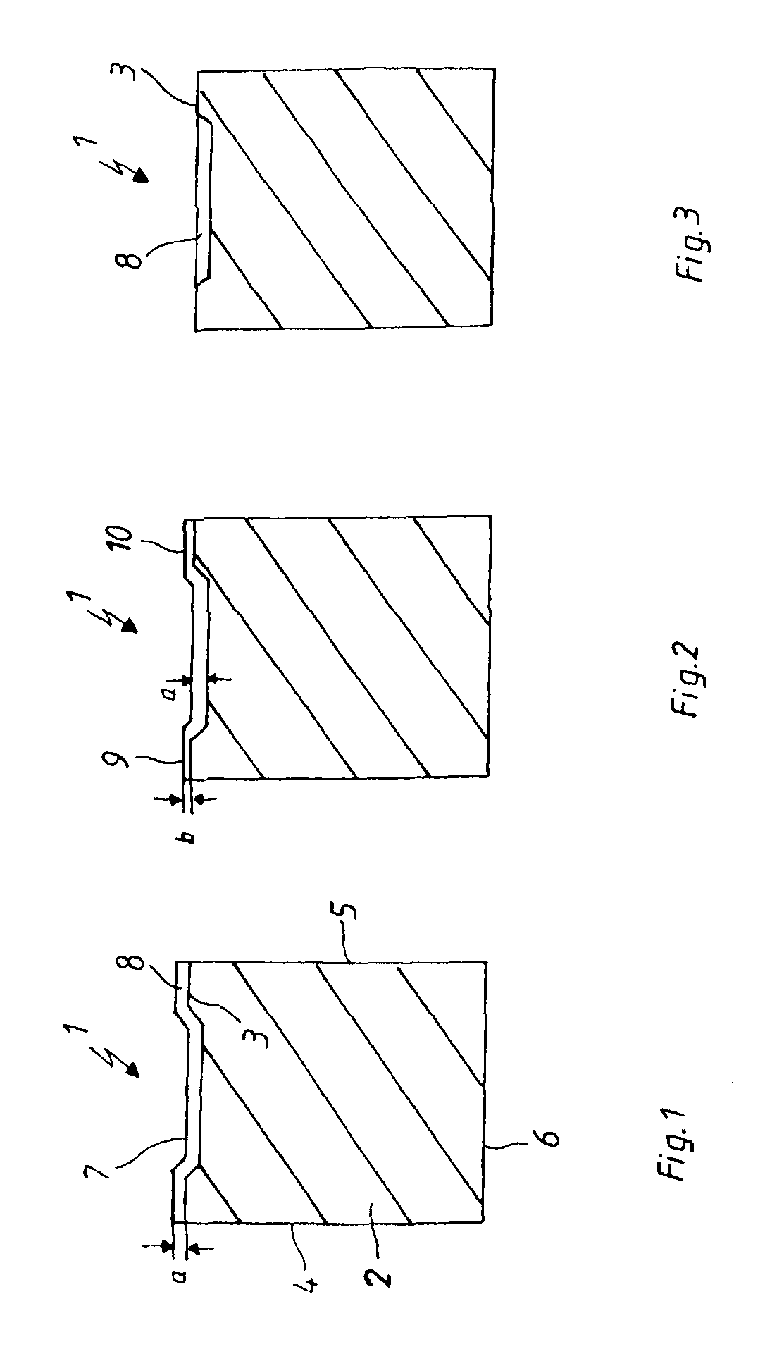
[0019]FIG. 1 shows a piston ring 1 in cross-section, having a main body 2, which exhibits a contact surface 3, an upper 4 and a lower flank surface 5 along with an inner peripheral surface 6. In the area of the contact surface 3 a chamber configuration 7 is incorporated. The contact surface 3 including chamber configuration 7 is provided with a PVD coating 8, in this example on the basis of CrN. On account of the precipitation properties of PVD coatings the covering coat 8 reproduces exactly the contour of contact surface 3 and chamber configuration 7 lying underneath. It can be recognized that the chamber configuration 7 is only partially filled with the PVD coating 8. The coating thickness ‘a’ of the PVD covering coat 8 is consequently the same both on the edge areas 8, 9 and also within the chamber configuration 7. In this example they have a thickness of 40 μm.

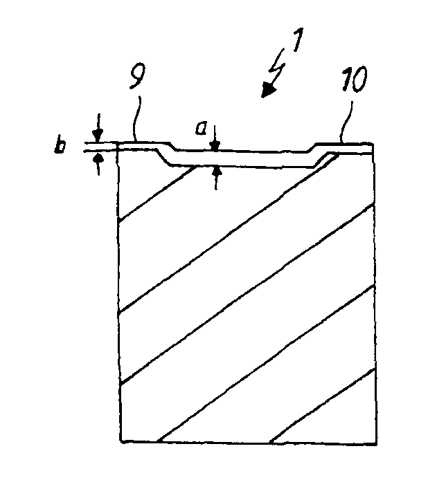
[0020]FIG. 2 shows the piston ring 1 according to FIG. 1 after having been machined. The coating thickness ‘a’ recognize...


PUM


Abstract

A piston ring having a base body, which comprises a running surface provided with at least one chamber, an upper and a lower flank surface, and an inner circumferential surface, wherein the running surface is provided with at least one PVD layer such that the same is adjusted to the contour of the running surface without completely filling the chamber, wherein the respective edge region is provided with a layer thickness, b that is reduced compared to the layer thickness, a of the chamber as a function of the configuration of the chamber.

Description

BACKGROUND OF THE INVENTION[0001]1. Technical Field[0002]The invention concerns a piston ring, having a main body, which exhibits a contact surface provided with at least one chamber configuration, one upper and one lower flank surface along with one inner peripheral surface.[0003]2. Related Art[0004]A piston ring as well as a process for producing the same may be gleaned from DE 103 59 802 B3. The piston ring contains a contact surface provided with a contact surface profile along with one upper and one lower flank surface, wherein at least the contact surface is provided with a vapor deposit coating, in such a way that a portion of the contact surface is provided with a removable mask, so that after production of the vapor deposit coating and removal of the mask a substantially sharp-edged contact edge is provided between the contact surface and at least one of the flank surfaces.[0005]In order to achieve good oil consumption and break-out behavior it is necessary for the lower ed...

Claims


Application Information

Patent Timeline
Patent Type & Authority Patents(United States)
IPC IPC(8): F16J9/26
CPCF16J9/12F16J9/26
Inventor ESSER, JOHANNESBRILLERT, HANS-RAINER
Owner FEDERAL MOGUL BURSCHEID
Why Eureka
Try Eureka