Bi-directional high side current sense measurement

a high-current sense, bi-directional technology, applied in the direction of resistance/reactance/impedence, instruments, fault locations, etc., can solve the problem that presence makes the measurement less accura

Active Publication Date: 2012-08-07
MICROCHIP TECH INC
View PDF3 Cites 7 Cited by
  • Summary
  • Abstract
  • Description
  • Claims
  • Application Information

AI Technical Summary

Problems solved by technology

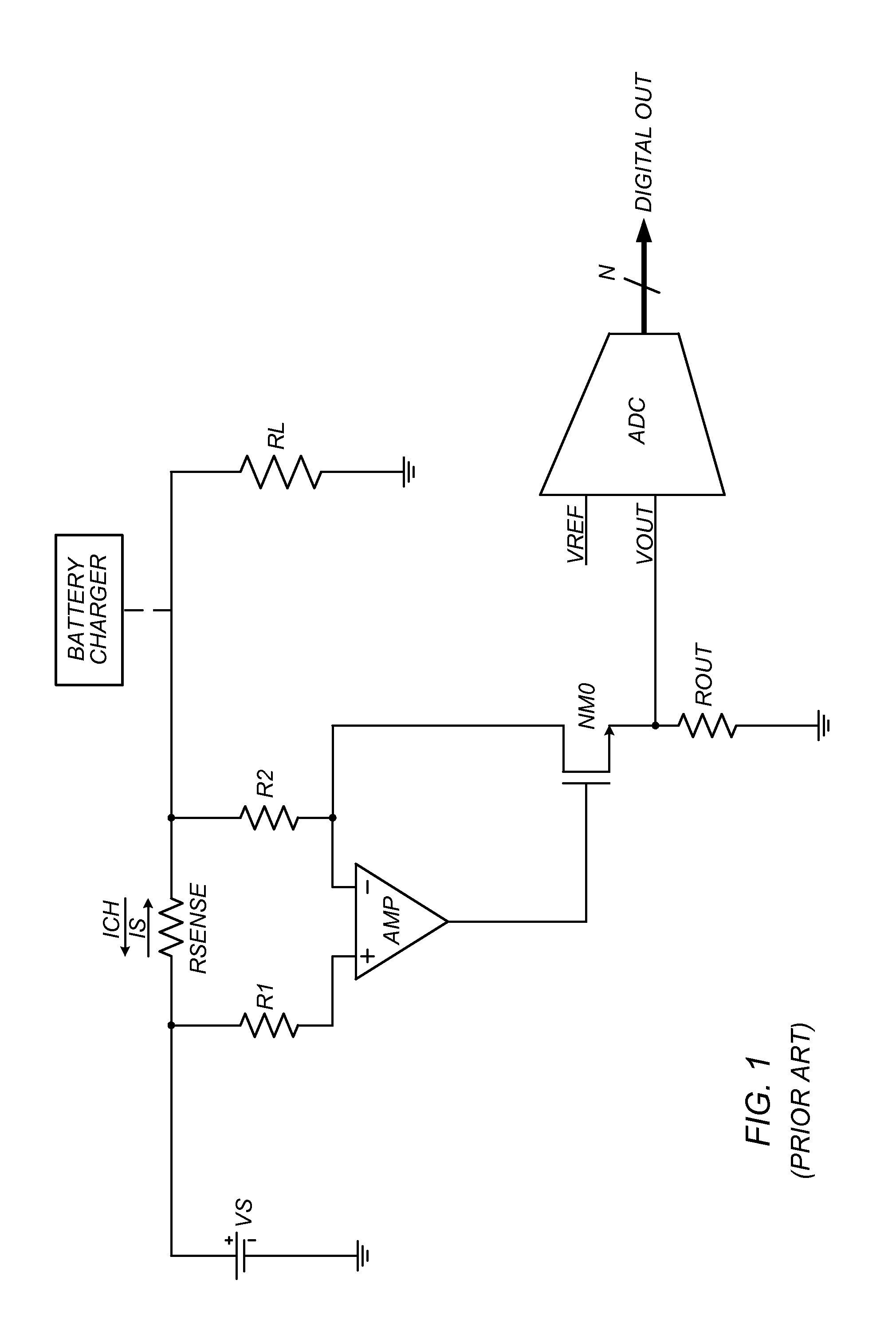
The amplifier constitutes an error source in the signal path, and hence, its presence makes the measurement less accurate.

Method used


Image

  • Bi-directional high side current sense measurement
  • Bi-directional high side current sense measurement
  • Bi-directional high side current sense measurement

Examples


embodiment 400

[0050]FIG. 4 shows an embodiment 400 of ADC 310 in terms of a delta-sigma topology. However, other ADC topologies may be used as well.

[0051]ADC embodiment 400 includes circuit 410, an integrator 415, a comparator 420, a counter 425 and a feedback unit 430.

[0052]The circuit 410 operates on the voltage drop Vsense(t) and a feedback signal VF(t) to generate a difference signal Vdiff(t) according to the expression:

Vdiff(t)=Vsense(t)−VF(t).  (1)

[0053]In some embodiments, circuit 410 also receives a voltage offset Voffset, in which case the difference signal Vdiff(t) is generated according to the expression:

Vdiff(t)=Vsense(t)−VF(t)+Voffset.  (2)

[0054]Integrator 415 continuously integrates the difference signal to generate an intermediate signal Y(t).

[0055]Comparator 420 operates on the intermediate signal Y(t) to generate a digital output signal (dout) that indicates whether the intermediate signal is positive or negative at each active edge of a clock signal. (The active edges may be the...

embodiment 300

[0115]FIG. 12 shows an alternative embodiment 300′ for the system of FIG. 3. The alternative embodiment 300′ includes resistors R1 and R2 coupled, respectively, between the ends of the sense resistor RSENSE and the inputs of the ADC 310. The resistors R1 and R2 may serve to limit the bandwidth of the Vsense signal. Furthermore, the resistors R1 and R2 may provide a measure of protection from electrostatic discharge (ESD) events. Resistors R1 and R2 are preferably equal (or approximately equal) in resistance. A similar alternative embodiment is contemplated for the system of FIG. 7, i.e., where resistors R1 and R2 couple, respectively, between the ends of the sense resistor and the inputs of front end 710.


PUM


Abstract

A system for measuring a voltage drop between two nodes in an electrical circuit, comprising a switched capacitor integrator (SCI), a comparator and a counter. The SCI alternately (a) captures charge onto a set of sampling capacitors and (b) selectively accumulates / transfers the charge onto a pair of integration capacitors, where the charge includes a first portion that is based on the voltage drop and a second portion that depends on a digital indicator signal. The comparator generates the digital indicator signal based on whether an analog output of the SCI is positive or negative. The counter counts a number of ones occurring in the digital indicator signal during a measurement interval. At the end of the measurement interval, the count value represents a measure of the voltage drop. Knowing the resistance between the two nodes, the voltage drop may be converted into a current measurement.

Description

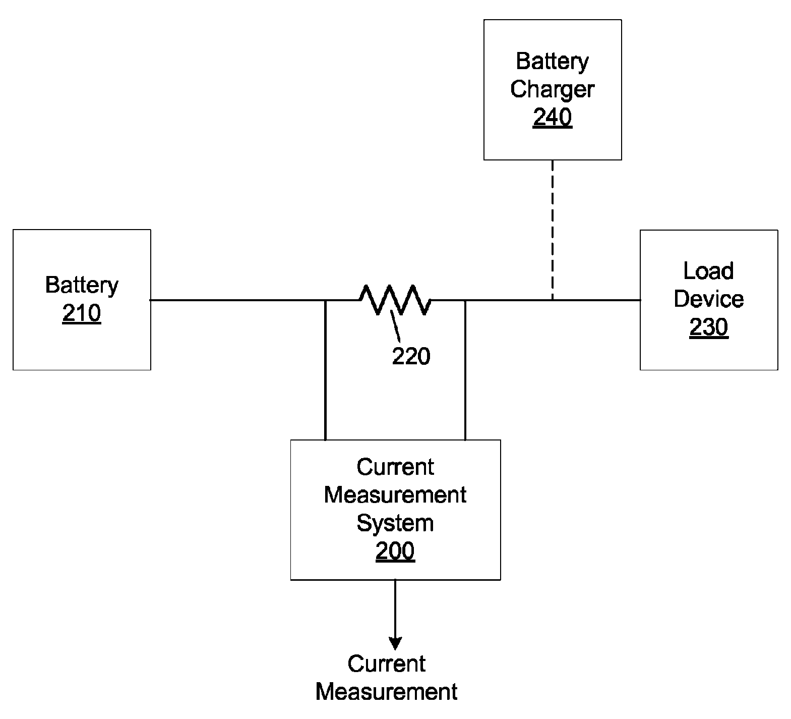
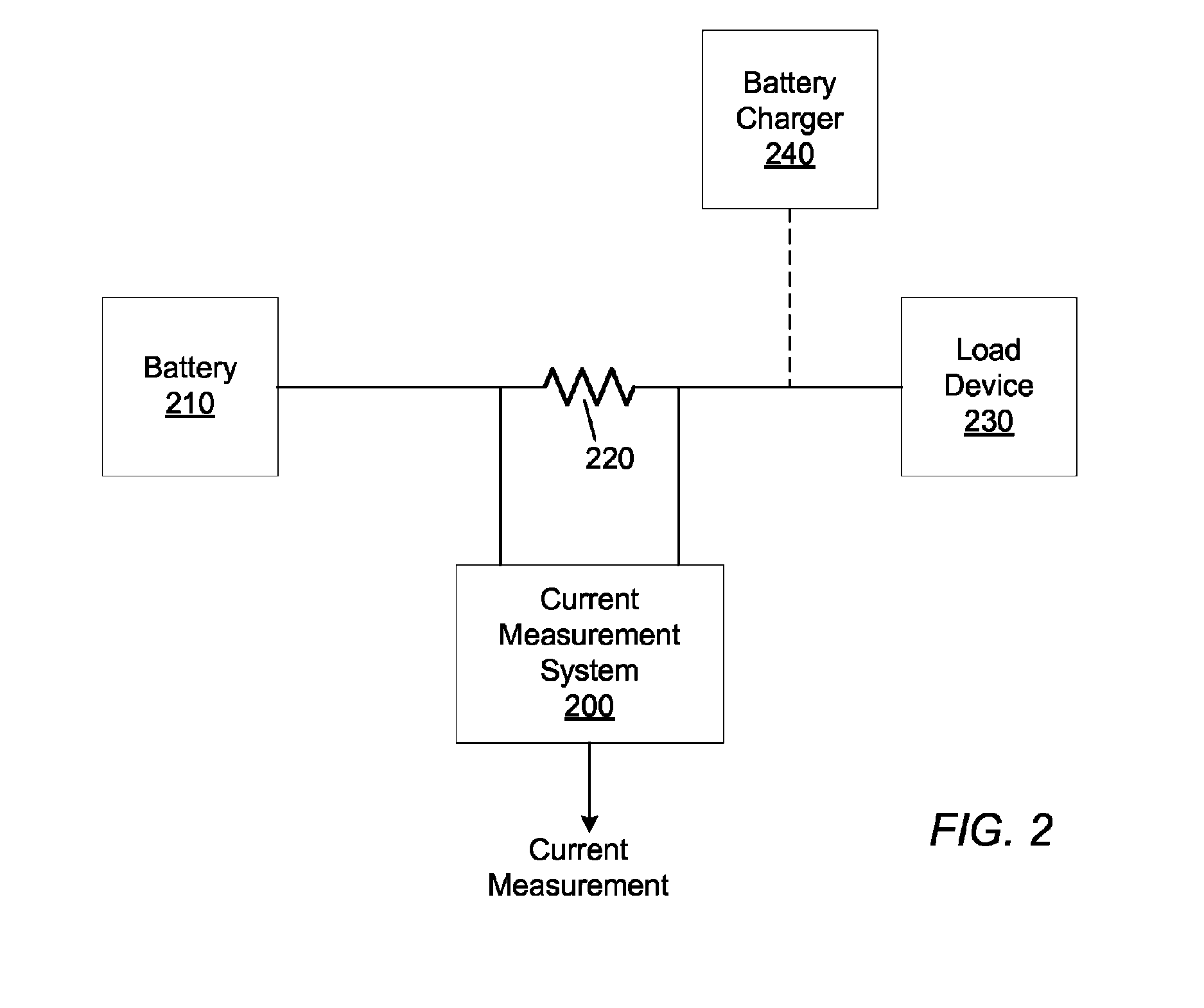
BACKGROUND OF THE INVENTION[0001]1. Field of the Invention[0002]This invention relates generally to the field of measurement circuit design, and more particularly, to an improved system and method for measuring the charging and discharging current in a battery-containing electrical system.[0003]2. Description of the Related Art[0004]Measurements are often performed to determine the total power being delivered by a battery to a load, or to determine the charging and discharging current of a battery system. In performing such measurements, it is desirable to accurately measure very small drops across a sense resistor that is carrying current from the battery to the load or from a charger to the battery. Both sides of the resistor may be at very high voltages depending on the battery used. Conventional Lithium ion (Li-ion) batteries in computers have DC voltages of 12V and higher. The drop across the sense resistor can be anywhere from microvolts to 100 mV.[0005]According to the prior ...

Claims


Application Information

Patent Timeline
Patent Type & Authority Patents(United States)
IPC IPC(8): G01R31/08
CPCG01R19/10G01R1/203
Inventor RALLABANDI, MADAN G.MCLEOD, SCOTT C.
Owner MICROCHIP TECH INC
Why Eureka
Try Eureka