Electromigration testing and evaluation apparatus and methods

a technology of electromigration and testing method, applied in the direction of instruments, fault location, and fault location by increasing the destruction at fault, can solve the problems of integrated circuit failure, voids in the interconnect structure nucleation and growth, etc., to reduce the cost of testing and evaluation, short testing time, and short testing time

Active Publication Date: 2012-08-07
NXP BV
View PDF5 Cites 19 Cited by
  • Summary
  • Abstract
  • Description
  • Claims
  • Application Information

AI Technical Summary

Benefits of technology

[0015]With the nucleation of a void in the first layer, the electrical resistance of the interconnect structure in the section of the void exhibits a step resistance-increase, but not to an infinite value. Afterwards, under continued stress, the resistance increases progressively according to the progress of electromigration-induced conductor-material diffusion leading to a one-dimensional growth of the void in the first layer. The electromigration testing method of the invention comprises measuring a quantity indicative of this increasing resistance during at least three respective stress time spans after the occurrence of the step resistance-increase. This way, deriving the electromigration characteristics of the DUT is made possible.
[0016]Consequently, it is not necessary to wait for a long test time at low temperature or low current density to determine the TTF, which corresponds to the time span required until reaching the step-shaped resistance-increase. The step resistance-increase can be forced to occur fast under a correspondingly stringent first stress condition, because the actual testing only starts afterwards. In particular, the method allows using one and the same first stress condition for all devices under test in the parallel testing of a large number of samples. For key information required for determining electromigration parameters is in this method obtained after the TTF, i.e., after the step-resistance increase. Thus, it becomes possible to let the duration of the electromigration testing not depend on the longest TTF within the group of devices under test, but, in practice, on a testing procedure after TTF. The electromigration testing method achieves testing times, which are shorter by a factor of at least 5 in comparison with electromigration testing methods that measure the TTF.
[0018]In summary, the method allows performing an electromigration test in much shorter time than known electromigration testing methods, without loss of information or accuracy. It is therefore possible to accelerate the optimization of the interconnect manufacturing process so that the conductor electromigration kinetics remains compatible with a required product lifetime. This allows reducing the time and cost for electromigration testing and thus fabricating integrated-circuit devices with a lower overall cost.
[0029]This embodiment achieves a particularly short testing time and allows reducing the cost for testing and evaluation.
[0030]To achieve particularly short testing times, the first temperature value of the first stress conditions is chosen higher than any of the temperature values used in the stress conditions after occurrence of the step-resistance change, and, as an alternative or in combination with that, the first current density value of the first stress conditions is higher than any of the current density values used in the stress conditions after occurrence of the step-resistance change. This embodiment has the advantage that the first stress time span can be made particularly short. Thus, the step resistance-increase is preferably forced by using a most accelerated stress condition, followed by subsequent stress conditions with reduced temperature and / or current.
[0038]This method allows achieving a reliable step detection and applying a criterion for a suitable stress time span after the occurrence of the step resistance-increase based on the same technique. Only the parameters of the relative change and of the time window used for detecting step need to be changed between the phases before and after the occurrence of the step resistance-increase. Before, the time window is preferably a moving time window. After the occurrence of the step resistance-increase, the time window suitably has a fixed starting point, which is the beginning of a respective stress time span.

Problems solved by technology

Electromigration is thus known to cause a nucleation and growth of voids in the interconnect structure.
Large enough voids can lead to open circuits, causing the integrated circuit to fail.

Method used


Image

  • Electromigration testing and evaluation apparatus and methods
  • Electromigration testing and evaluation apparatus and methods
  • Electromigration testing and evaluation apparatus and methods

Examples


Embodiment Construction

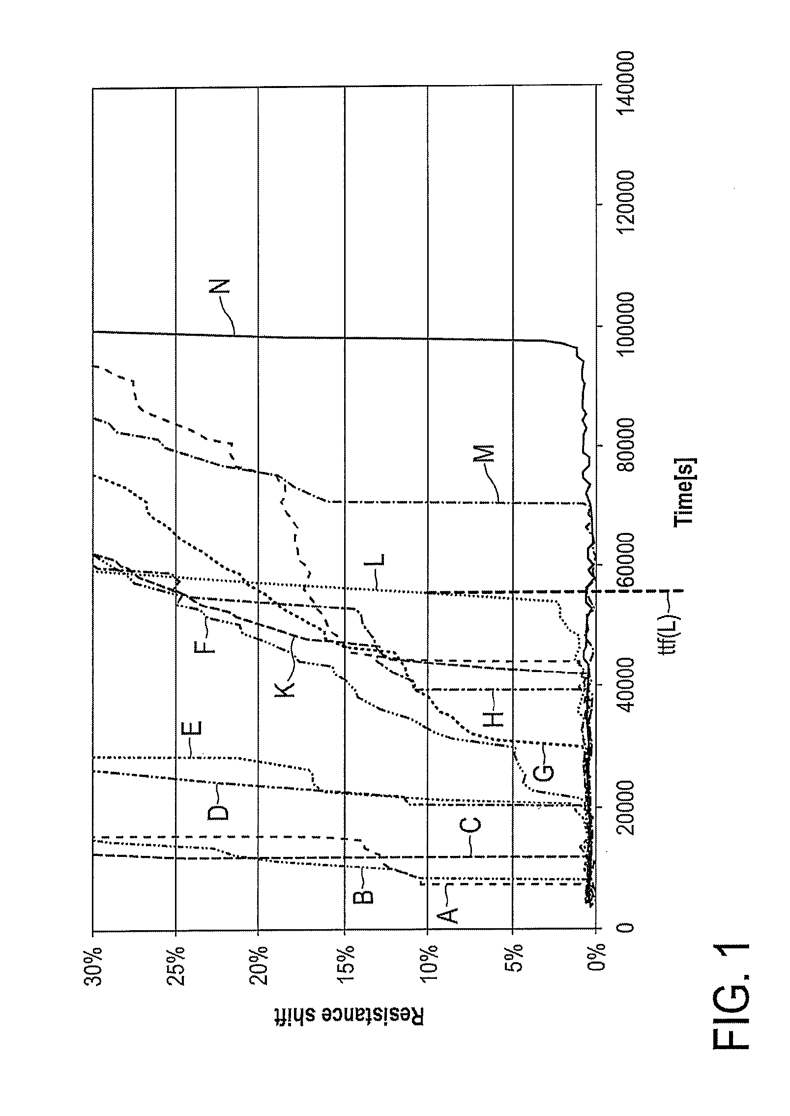
[0104]FIG. 1 shows a diagram illustrating the evolution of the electrical resistance of an interconnect structure in time under exemplary stress conditions for a number of nominally identical samples taken from a specific wafer lot.

[0105]The resistance change is plotted on the y-axis in relative units between 0 and 30%. On the x-axis, the time is plotted in units of seconds.

[0106]For the resistance measurements, which are shown in FIG. 1, the samples were all subjected to stress conditions formed by a temperature of 300° C. and a current density of 1.5 MA / cm2 in the interconnect structure. Each resistance trace plotted in the diagram of FIG. 1 corresponds to one sample.

[0107]It is clearly visible from FIG. 1 that the different samples exhibit quite different time-to-failure (TTF) values. The TTF refers to the time span from the beginning of the measurement to reaching a step resistance increase. Some samples exhibit a TTF value, which is lower than 10 000 seconds. Exemplary resistan...


PUM


Abstract

The present invention relates to electromigration testing and evaluation methods and apparatus for a device under test with an interconnect structure. The method comprises forcing the occurrence of a step resistance-increase of the interconnect structure due to electromigration in the first layer and subsequently subjecting the interconnect structure to at least three respective predetermined stress conditions while concurrently measuring a test quantity indicative of an electrical resistance of the interconnect structure. The method allows performing an electromigration test in much shorter time than known electromigration testing methods, without loss of information or accuracy. It is therefore possible to accelerate the optimization of the interconnect manufacturing process so that the conductor electromigration kinetics remains compatible with a required product lifetime. This allows reducing the time and cost for electromigration testing and thus fabricating integrated-circuit devices with a lower overall cost.

Description

FIELD OF THE INVENTION[0001]The present invention relates to an electromigration testing method and apparatus and an electromigration evaluation method and apparatus.BACKGROUND OF THE INVENTION[0002]In the fabrication of integrated circuits, individual devices such as transistors on a wafer are connected by interconnect structures to perform desired functions of the integrated circuits. The interconnect structures are typically arranged on different interconnect levels, which are connected through vias.[0003]Electromigration in interconnect structures of integrated-circuits is known as an atomic movement (flux) of conductor material due to electric current flow. It is observed to occur at rather high current densities. Under a high current density, atoms constituting the interconnect structure are pushed by traveling electrons, so that a constant flux of matter is generated. This flux will remain constant, unless a discontinuity is encountered. A flux divergence is likely to induce ...

Claims


Application Information

Patent Timeline
Patent Type & Authority Patents(United States)
IPC IPC(8): G01R27/08
CPCG01R31/2858
Inventor FEDERSPIEL, XAVIER
Owner NXP BV
Why Eureka
Try Eureka