
Bearing

Active Publication Date: 2012-08-14
CONTITECH VIBRATION CONTROL
View PDF7 Cites 5 Cited by
  • Summary
  • Abstract
  • Description
  • Claims
  • Application Information

AI Technical Summary

Benefits of technology

[0010]The object of the invention is to configure a bearing of the aforementioned type which is easily adjustable such that the stiffness of the bearing can be increased at any time while avoiding the aforementioned disadvantages.
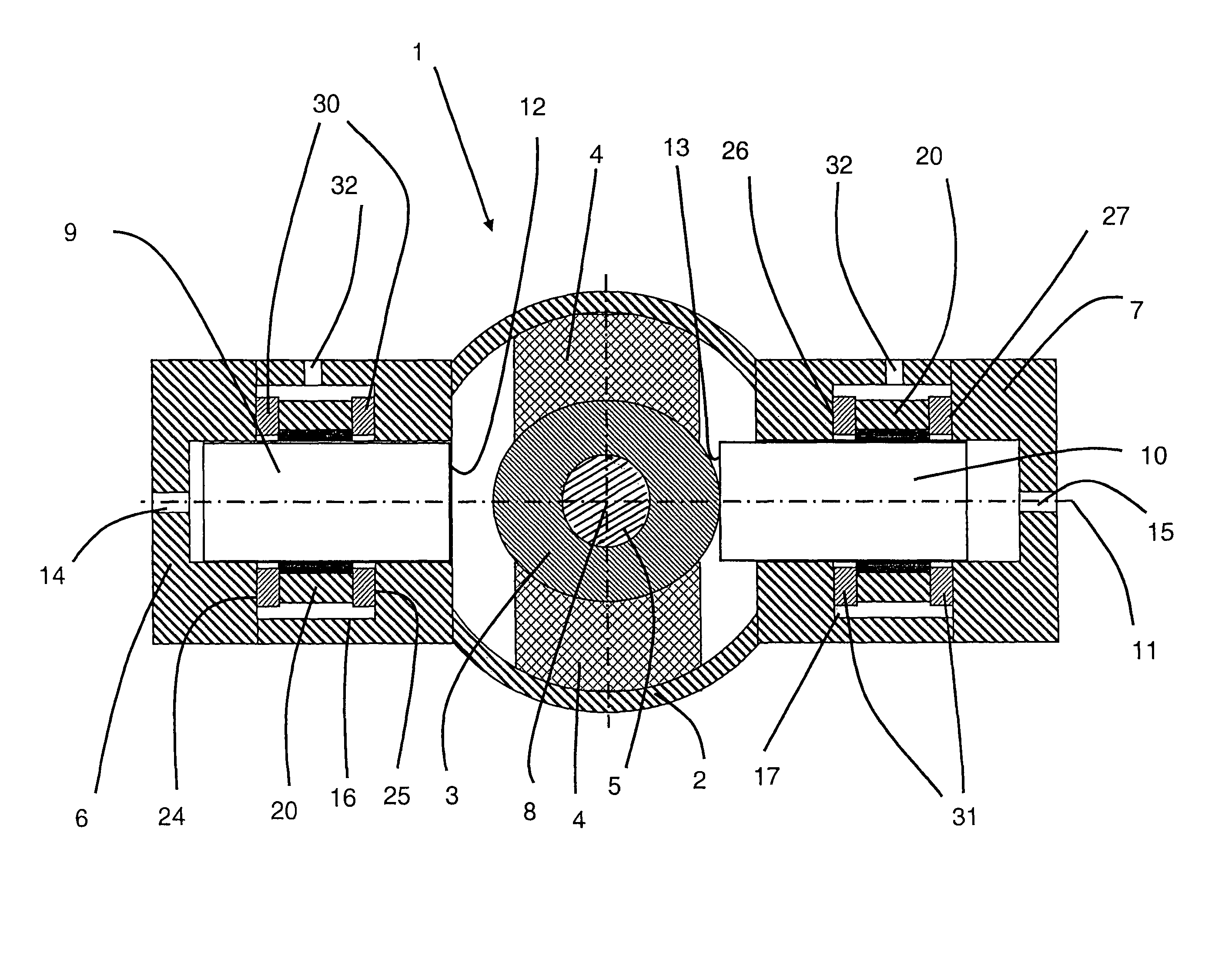
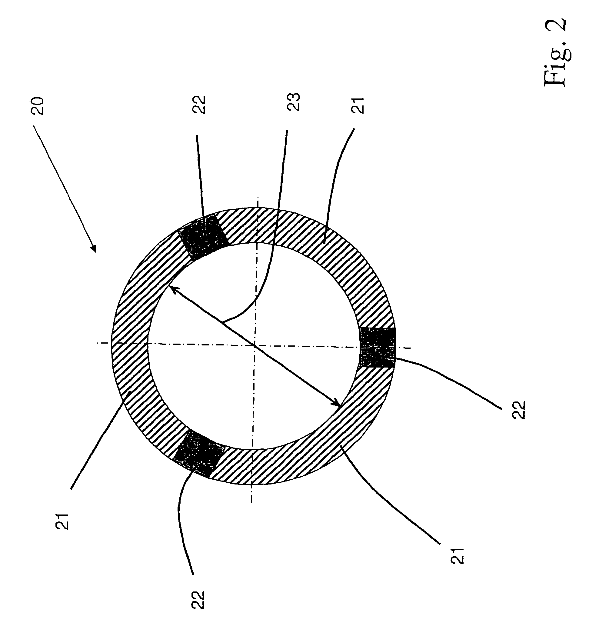
[0013]This arrangement allows to securely clamp the adjusting elements in the particular desired position with a relatively low pressure, for example by pneumatic pressure. For this reason, only a small pressure, which displaces the adjusting elements towards the inner bearing sleeve, is needed on the end faces of the adjusting elements. The adjusting elements are fixed by the friction acting between the clamping rings and the adjusting elements. It is also advantageously possible, by controlling the radial clamping ring pressure, to damp a relative movement between the adjusting elements and the clamping rings by adjusting the pressure so that a variable sliding friction prevails between the clamping rings and the adjusting elements. An individual control of the two adjusting elements independently of one another is also possible.
[0015]This arrangement affords the advantage that, when a pressure is applied to the clamping rings, the bearing does not become too stiff, since the elastomer bodies in the slots allow a relative axial movement of the adjusting pistons. The overall stiffness of the bearing then results from superimposing the stiffness of the elastomer body between the inner and outer bearing sleeves and the stiffness of the elastomer bodies in the intermediate spaces between the clamping rings and the slot faces.
[0017]It is not necessary here to apply pressure to the adjusting elements in order for them to strike against the inner bearing sleeve. This embodiment means that the adjusting elements act in both directions of movement along their common axis, that is to say in pull and push. As a result, the radial pressure on the clamping rings needed for clamping can be reduced. Such an embodiment also prevents the adjusting elements from striking against the inner bearing sleeve when they are subjected to pressure.
[0018]The fundamental stiffness of the bearings according to the invention can advantageously be made much softer than that of conventional bearings. An improved ride comfort is consequently achieved. With bearings designed in this way the bearing stiffness can be multiplied at any time even with relatively low pressures and with compressible pressure media.

Problems solved by technology

This means that one of the two spring elements is no longer operative so that the stiffness of the assembly bearing is increased.
A disadvantage of the adjustable bearings cited is that they have a very complex and costly construction.
Here, the pressure required for fixing can only be fully built up once both adjusting elements are resting against their opposing stop faces.
Disadvantageous is here that the pressure must be fully developed at the instant at which the inner bearing sleeve is to be fixed and that a compressible medium, such as air, cannot be used.

Method used


Image

  • Bearing
  • Bearing
  • Bearing

Examples


Embodiment Construction

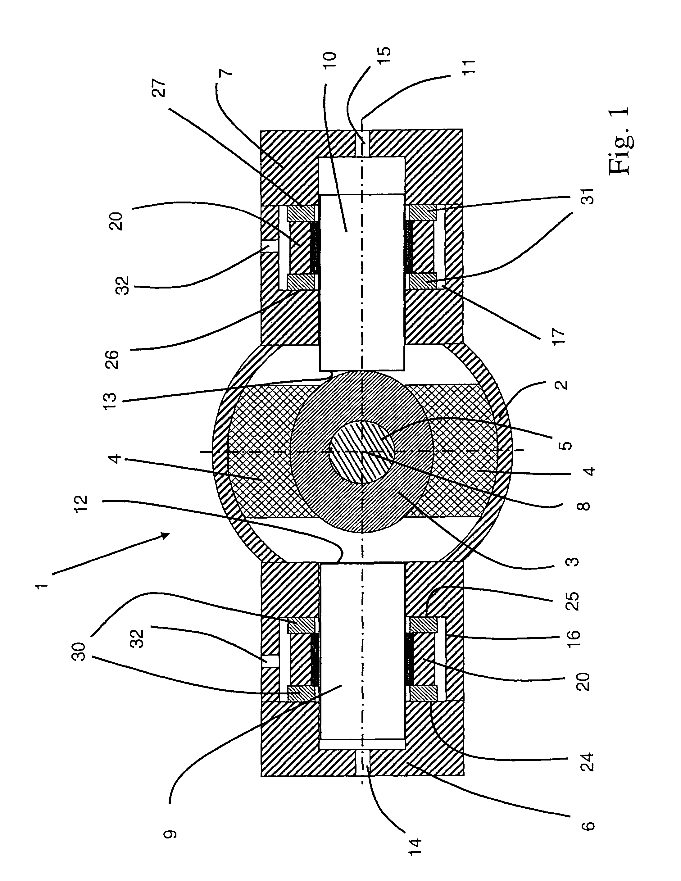
[0023]The bearing 1 represented in FIG. 1 is embodied as a chassis bearing and comprises a multi-part outer bearing sleeve 2, an inner bearing sleeve 3 and an elastomer body 4 arranged between the outer bearing sleeve 2 and the inner bearing sleeve 3. While the elastomer body 4 is connected via the outer bearing sleeve 2 to the wheel suspension (not shown here), the inner bearing sleeve 3 is fixed by a pin 5 to the chassis (not shown here).

[0024]The chassis bearing 1 further has two chambers (6, 7) which are arranged on the outer bearing sleeve 2. The chambers (6, 7) are arranged to be separate from one another and symmetrically on both ends of the longitudinal axis 8 of the inner bearing sleeve 3.

[0025]As adjusting element, each chamber (6, 7) has an adjusting piston (9, 10) which is arranged on a common transverse axis 11 of the inner bearing sleeve 3.

[0026]On their end facing the inner sleeve, the adjusting pistons (9, 10) have a stop face (12, 13), which faces can lie on the inn...


PUM


Abstract

The invention relates to a bearing, in particular a chassis bearing for the rear axle of a motor vehicle, with an outer bearing sleeve, an inner bearing sleeve, at least one elastomer body arranged between the outer and inner bearing sleeves and two chambers which are arranged laterally opposite each other on the outer bearing sleeve. The chambers each have an adjusting element. The adjusting elements are displaceable. When subjected to pressure, the adjusting elements are displaced inwardly against the inner bearing sleeve. The adjusting elements can be clamped in their axial position by clamping rings which can be reduced in size radially, for example by means of air pressure. The inner bearing sleeve is thereby fixed and the rigidity of the bearing increased.

Description

RELATED APPLICATIONS[0001]This application is the national stage of PCT / EP 2006 / 004710, filed May 18, 2006, designating the United States and claiming priority from German patent application no. 10 2005 028 563.5, filed Jun. 21, 2005, the entire contents of which are incorporated herein by reference.FIELD OF THE INVENTION[0002]The invention relates to a bearing, in particular a chassis bearing for the rear axle of a motor vehicle, with an outer bearing sleeve, an inner bearing sleeve, at least one elastomer body arranged between the outer bearing sleeve and the inner bearing sleeve, and two chambers, which are arranged on the outer bearing sleeve. The main axes of the chambers form a common transverse axis with a transverse axis of the inner bearing sleeve and the chambers are arranged separately from one another and symmetrically on both sides of the longitudinal axis of the inner bearing sleeve and each has an adjusting element. The adjusting elements are arranged on the common tr...

Claims


Application Information

Patent Timeline
IPC IPC(8): F16M1/00
CPCB60G7/006F16F1/387F16F13/26B60G2204/4106B60G2204/45
Inventor EBERHARD, GUNTERHOLST, MEINERT
Owner CONTITECH VIBRATION CONTROL
Learn More