Method and apparatus for an ion transfer tube and mass spectrometer system using same

a mass spectrometer and ion transfer technology, applied in the field of mass spectrometer systems, can solve the problems of less-than-optimal conditions for transferring ions across the vacuum interface, increased gas load, and suppression of certain ions based on their charge state, so as to reduce the effect of exit turbulence, reduce the occurrence of fragmentation of fragile ions, and increase the transmission of multiply charged ions

Active Publication Date: 2012-08-14
THERMO FINNIGAN
View PDF32 Cites 28 Cited by
  • Summary
  • Abstract
  • Description
  • Claims
  • Application Information

AI Technical Summary

Benefits of technology

[0016]The increase in diameter at the outlet end of the capillary allows the gas to expand while still in the capillary which reduces the velocity at the exit end thereby reduces the effect of exit turbulence and, possibly, shockwaves. The point where the diameter increases occurs sufficiently far into the capillary, with respect to the outlet end of the capillary, that a laminar flow is established with its associated radial velocity profile. Some benefits that are observed are an increased transmission of multiply charged ions as well as a decreased occurrence of fragmentation of fragile ions. An added benefit is that a capillary in accordance with the present teachings can be machined both in a very well defined manner (e.g. by drilling with a drill diameter in the range of the ID to the OD of the capillary) and without increasing tooling costs.

Problems solved by technology

It is to be appreciated that this expansion may lead to less-than-optimal conditions to transfer ions across the vacuum interface, and could for instance lead to a suppression of certain ions based on their charge state.
Although the flow rate through the ion transfer tube may be increased by enlarging the tube bore (inner diameter), such enlargement of the ion transfer tube diameter results in an increased gas load that, in the absence of increased pumping capacity, causes the pressures in the vacuum chambers to increase as well.
Of course, increasing the number and / or capacity of the vacuum pumps also increases the cost of the mass spectrometer, as well as the power requirements, shipping weight and cost, and bench space requirements.
More generally, however, viscous drag against the tube interior will maintain the flow within the tube, and possibly exiting the tune, at sub-sonic velocities.
Unfortunately, this non-laminar and possibly turbulent flow exiting the ion transfer tube often results in many of the ions failing to flow into downstream apertures and chambers of the device.
Ions with lower mass-to-charge ratio (m / z) may be expected to be more susceptible to trajectory-bending effects of such fields, thereby resulting in (m / z)-selective ion loss.
This step leads to small irreproducible differences between capillary specimens.
The hypothesized resulting variable and uncontrolled flow exiting the conventional ion transfer tube may then lead to dispersal of ions away from a nominal instrumental trajectory thereby leading to either actual physical loss from the instrumental system or, possibly, fragmentation of fragile ions upon encountering regions of high RF voltage.
Providing a special tool to produce exact replicas that avoid such variations would lead to an expected increase in manufacturing costs.
However, not all apparatus configurations may admit such adjustments.

Method used


Image

  • Method and apparatus for an ion transfer tube and mass spectrometer system using same
  • Method and apparatus for an ion transfer tube and mass spectrometer system using same
  • Method and apparatus for an ion transfer tube and mass spectrometer system using same

Examples


Embodiment Construction

[0037]The following description is presented to enable any person skilled in the art to make and use the invention, and is provided in the context of a particular application and its requirements. Various modifications to the described embodiments will be readily apparent to those skilled in the art and the generic principles herein may be applied to other embodiments. Thus, the present invention is not intended to be limited to the embodiments and examples shown but is to be accorded the widest possible scope in accordance with the features and principles shown and described.

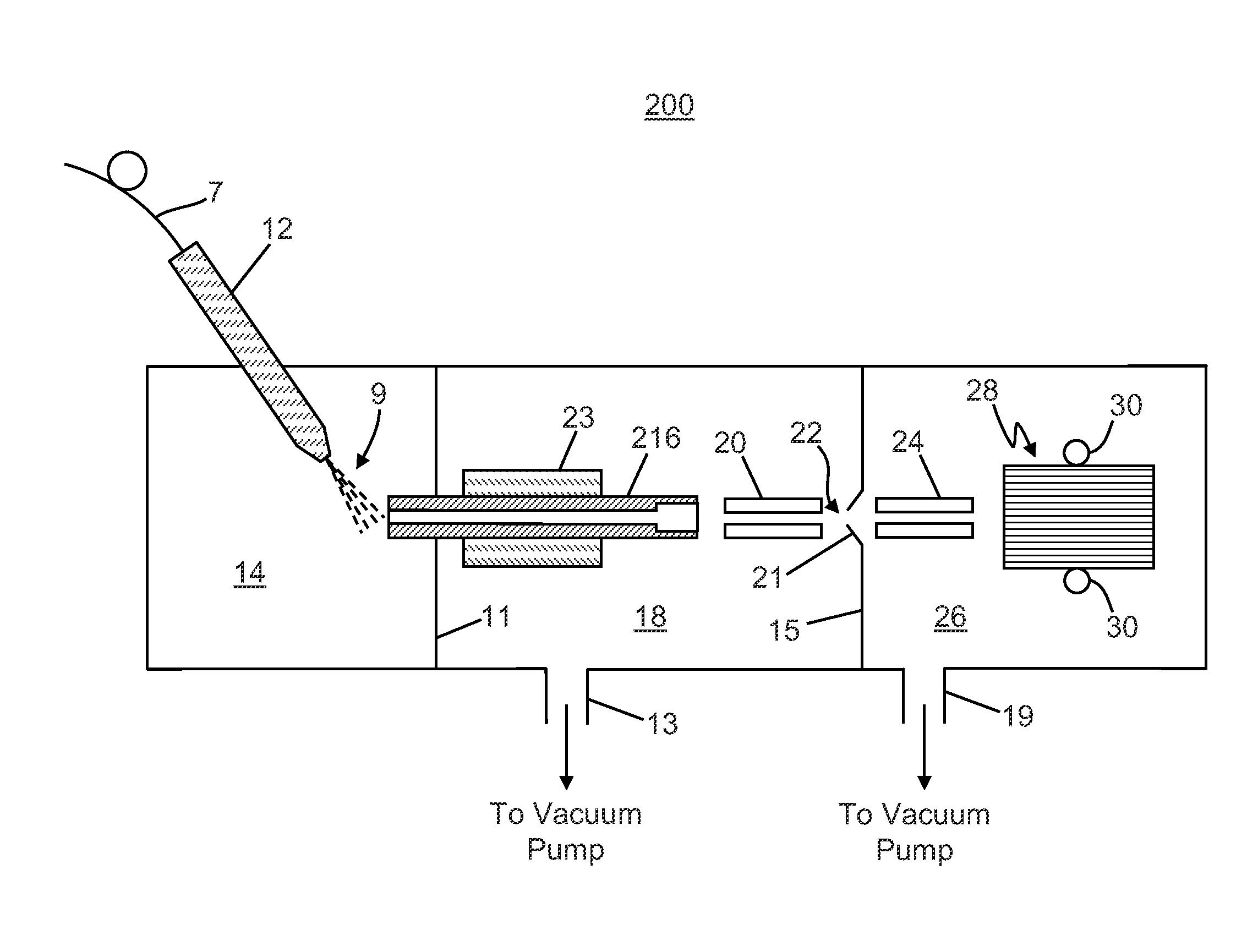
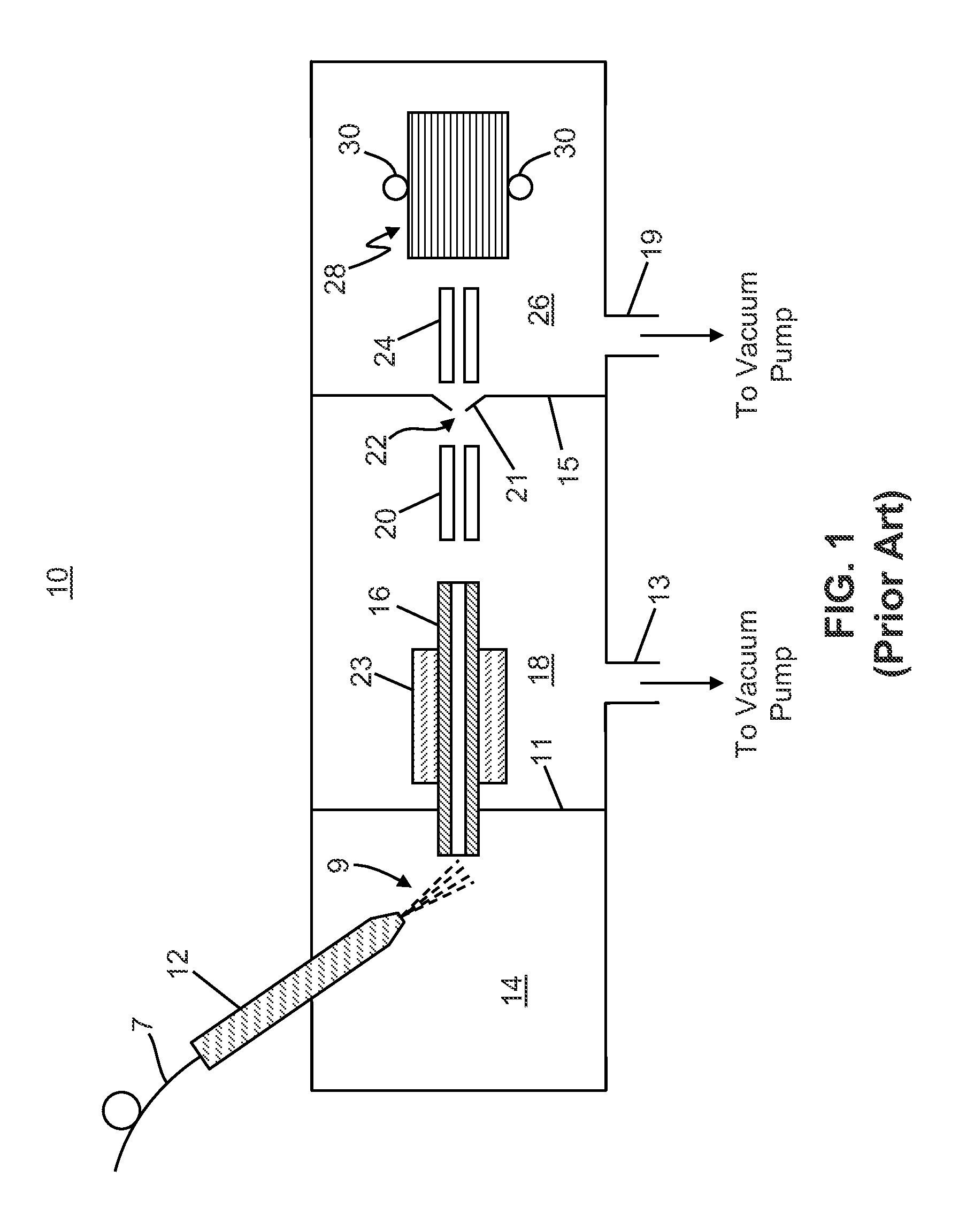
[0038]To more particularly describe the features of the present invention, please refer to FIGS. 3 through 18 in conjunction with the discussion below.

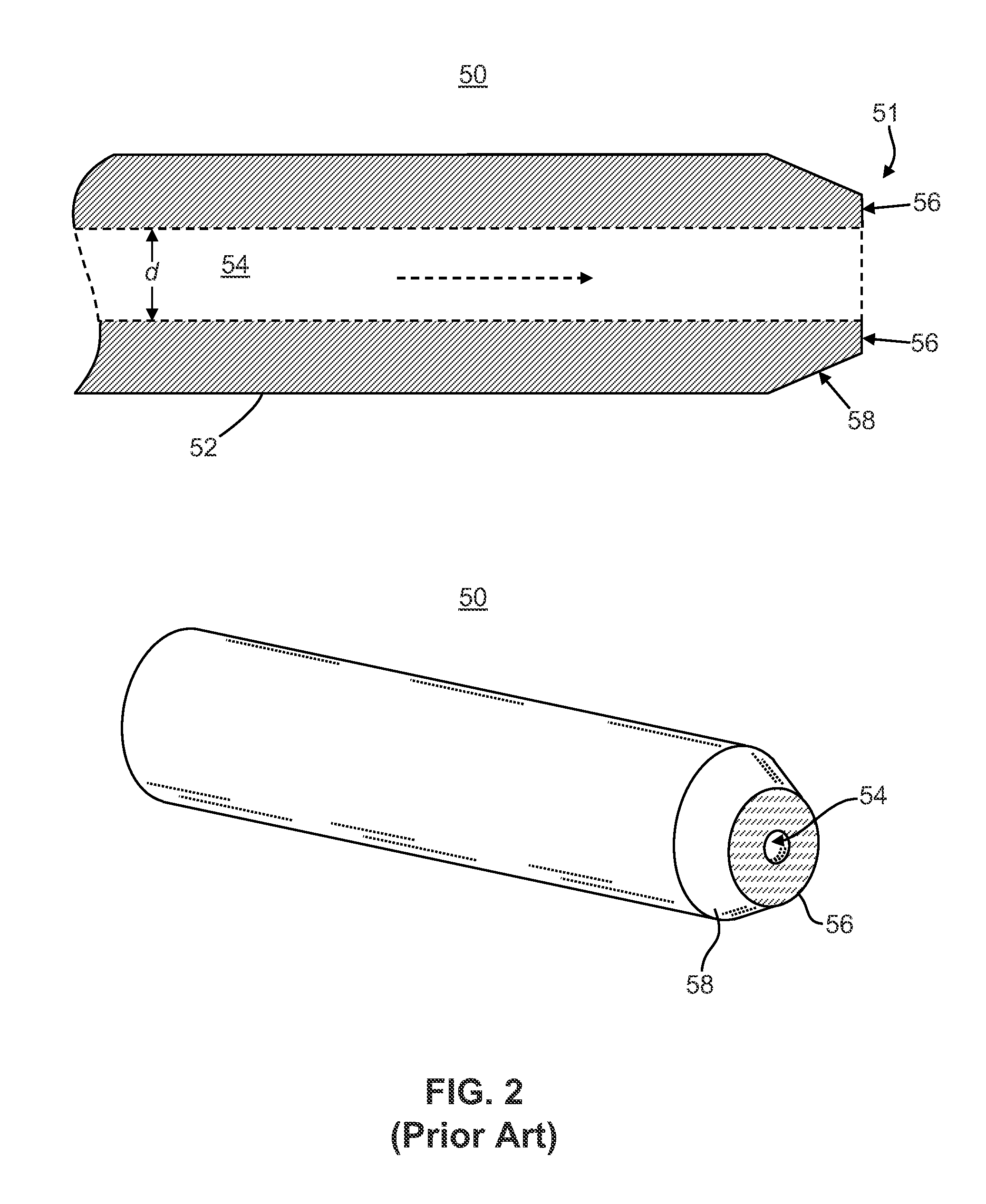
[0039]Referring to FIGS. 13 and 14, a heated capillary tube assembly 222 is illustrated. The capillary tube assembly includes a cylindrical heater 241 which is electrically heated via the heater wire 242. A capillary tube 243 extends axially through the heater. T...


PUM


Abstract

A method for analyzing a sample comprising the steps of: generating ions from the sample within an ionization chamber at substantially atmospheric pressure; entraining the ions in a background gas; transferring the background gas and entrained ions to an evacuated chamber of a mass spectrometer system using a single-piece capillary having an inlet end and an outlet end, wherein a portion of the capillary adjacent to the outlet end comprises an inner diameter that is greater than an inner diameter of an adjoining portion of the capillary; and analyzing the ions using a mass analyzer of the mass spectrometer system.

Description

FIELD OF THE INVENTION[0001]This invention generally relates to mass spectrometer systems, and more specifically to an ion transfer tube for transporting ions between regions of different pressure in a mass spectrometer.BACKGROUND OF THE INVENTION[0002]Ion transfer tubes are well-known in the mass spectrometry art for transporting ions from an ionization chamber, which typically operates at or near atmospheric pressure, to a region of reduced pressure. Generally described, an ion transfer tube typically consists of a narrow elongated conduit having an inlet end open to the ionization chamber, and an outlet end open to the reduced-pressure region. Ions formed in the ionization chamber (e.g., via an electrospray ionization (ESI) or atmospheric pressure chemical ionization (APCI) process), together with partially desolvated droplets and background gas, enter the inlet end of the ion transfer tube, traverse its length under the influence of the pressure gradient, and exit the outlet end...

Claims


Application Information

Patent Timeline
Patent Type & Authority Patents(United States)
IPC IPC(8): H01J49/04
CPCH01J49/0404
Inventor SPLENDORE, MAURIZIO A.WOUTERS, ELOY R.ATHERTON, PAUL R.DUNYACH, JEAN JACQUES
Owner THERMO FINNIGAN
Why Eureka
Try Eureka