System and method for positioning using signal transmit power and signal receive packet error ratio

a technology of transmit power and signal receive, applied in the field of radio frequency technologies, can solve the problems of inability to meet the needs of low-cost applications, large energy consumption, and inability to fully play gps in downtown areas, and achieve low-cost and micro-power consumption, simple but efficient positioning, and high-precision positioning. the effect of moving targ

Inactive Publication Date: 2012-08-14
WESTVALLEY DIGITAL TECH
View PDF11 Cites 1 Cited by
  • Summary
  • Abstract
  • Description
  • Claims
  • Application Information

AI Technical Summary

Benefits of technology

[0015]The present invention is directed to providing an economic and practical positioning system and method with a high precision by taking advantages of low cost and simple structure of the RFID.
[0016]One embodiment of the present invention provides a system for positioning using an active RFID tag. The system includes a ranging signal collecting unit, configured to collect ranging signals from a ranging signal transmitting unit, the ranging signal transmitting unit being configured to continuously and repeatedly transmit a predetermined number of ranging signal packets; a packet loss rate (PLR) calculating unit, configured to calculate the PLR of the ranging signals according to the number of received ranging signal packets received by the ranging signal collecting unit and the predicted number of data packets transmitted by an active RFID tag within a predetermined time period; and a position determining unit, configured to determine, based on a predetermined policy, the distance between the ranging signal transmitting unit and the ranging signal collecting unit according to the PLR and transmit power of the ranging signals. It should be noted that the active RFID tag may also be a common radio signal transceiver device. The active RFID tag differs from the common radio signal transceiver device in that it is mainly used for identification and positioning. Therefore, the active RFID tag needs to be cost efficient and small in size for easy carrying. In addition, for the purpose of energy saving, it needs to work in intermittent mode to reduce the duty cycle.
[0024]According to embodiments of the present invention, the method and system for positioning use low-cost and micro-power consumption active RFID tag and transceiver unit. With the method and system, high-precision positioning for a moving target can be simply achieved without adding any device. The maximum positioning errors indoor and outdoor are all less than 10% of the positioning range. This not only solves the problem of how to accurately position the search target in the search and rescue on land, on the sea, and in underground mine, which is practical. Meanwhile, the present invention also provides a new, economic, simple but efficient positioning method for other positioning applications.

Problems solved by technology

Obviously, the GPS receiving terminal and mobile communication terminal are costly, large, and energy-consuming, which is not suitable for low cost applications.
In addition, the GPS is not in full play in a downtown area with a high density of buildings, inside the buildings, and underground mine.
This is not suitable for positioning applications requiring low cost because the devices are expensive devices and large in size.
This is very difficult in rescuing, especially in frog and the night with a low visibility.
This method is simple, but is not accurate.
However, the RSSI produces a great error in signal strength test and there are many factors affecting the test.
Therefore, such signal strength test is far from accurate, especially in small-scale and short-distance positioning.
Because there is a high requirement on time synchronization between the signal source and signal receiver, this method is not practical.
As regards the positioning by measuring the TDOA between the signal source and signal receiver in case of different signals (radio frequency signal and ultrasonic signal), the cost is increased because two different signals are required.
In addition, with this method, the positioning accuracy is closely related to the precision in time difference test, which increases its application complexity and hinders its application.
Although ensuring safety in the underground mine and rescuing the victims in distress are two top issues for safe production in underground mine, only the area where the workers in the underground mine can be determined, far from accurate positioning.
Accordingly, in the event of an accident, the victims cannot be accurately positioned, which increases complexity of the rescue work.
Therefore, accurately positioning the workers trapped in the underground mine is a critical problem to be solved.
To sum up, the conventional positioning technology encounters problems such as high cost, weak practicality, and low positioning precision.

Method used


Image

  • System and method for positioning using signal transmit power and signal receive packet error ratio
  • System and method for positioning using signal transmit power and signal receive packet error ratio
  • System and method for positioning using signal transmit power and signal receive packet error ratio

Examples


fourth embodiment

[0117]According to the present invention, as regards a target in a three-dimensional space, the positioning of a target carrying the active RFID tag, referring to FIG. 9, the system for positioning the active RFID tag includes: an active RFID tag, control processor, coordinator, reference signal source, directional antenna 1, and directional antenna 2.

first embodiment

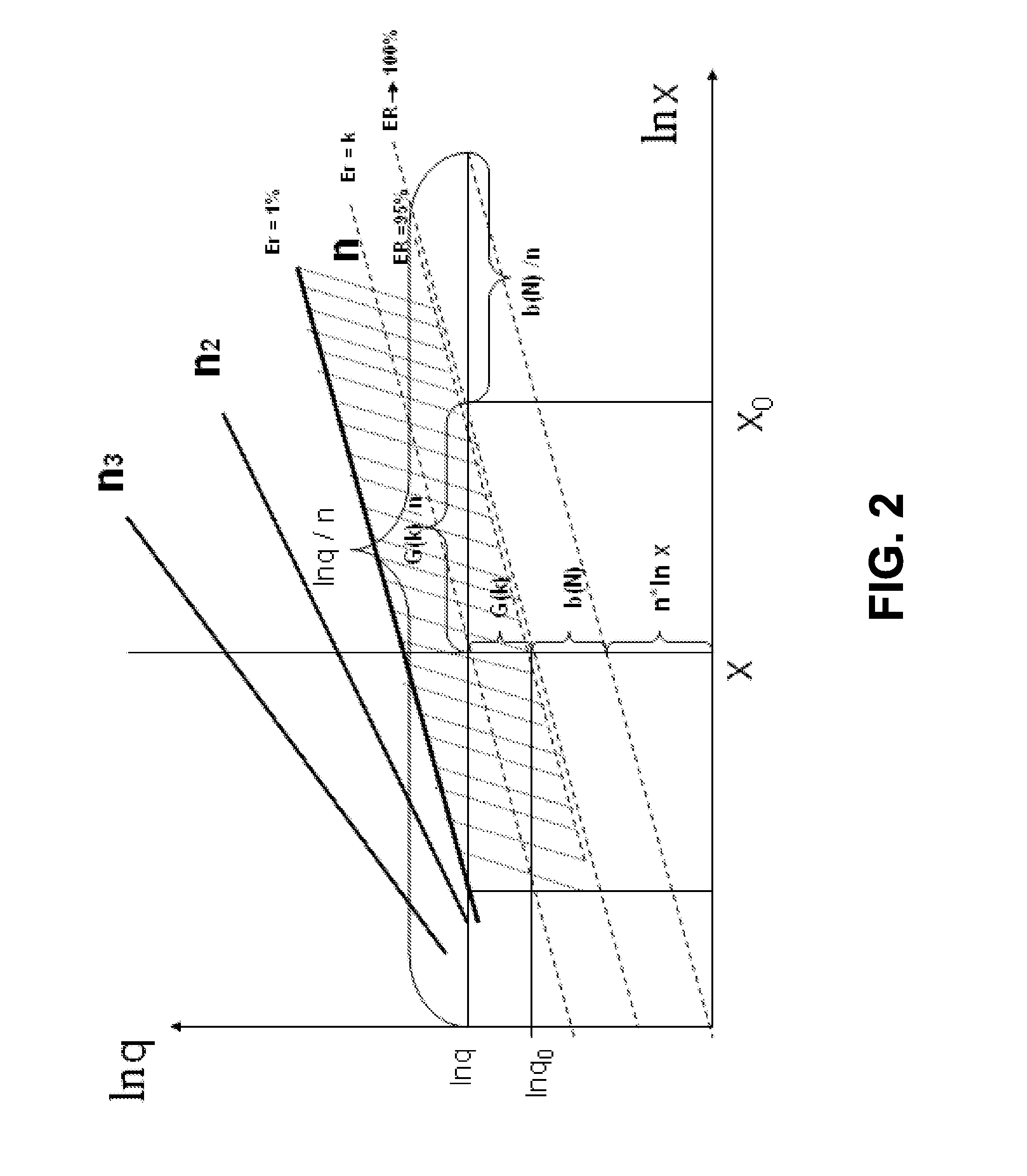
[0118]Step 1: Use the reference signal source to correct b(N) in the formula ln x=[ln q−G(Er)−b(N)] / n to determine b(Nnew), referring to the description of the

[0119]Step 2: The coordinator continuously sends wakeup signals to the active RFID tag in different direction on a wakeup channel (channel F1) by rotating the directional antenna 1.

[0120]Step 3: When the directional antenna rotates to the direction of the active RFID tag, the active RFID tag in the standby state receives wakeup signals from the coordinator on the wakeup channel with the interception time period. Upon receiving the wakeup signals, the active RFID tag switches to the working channel (channel F2) immediately to transmit the ranging signals in the pre-determined ranging signal transmission mode, or transmits the ranging signals in the pre-determined ranging signal transmission mode according to the information contained in the wakeup signals that is used for controlling the mode for the active RFID tag to transmit...

fifth embodiment

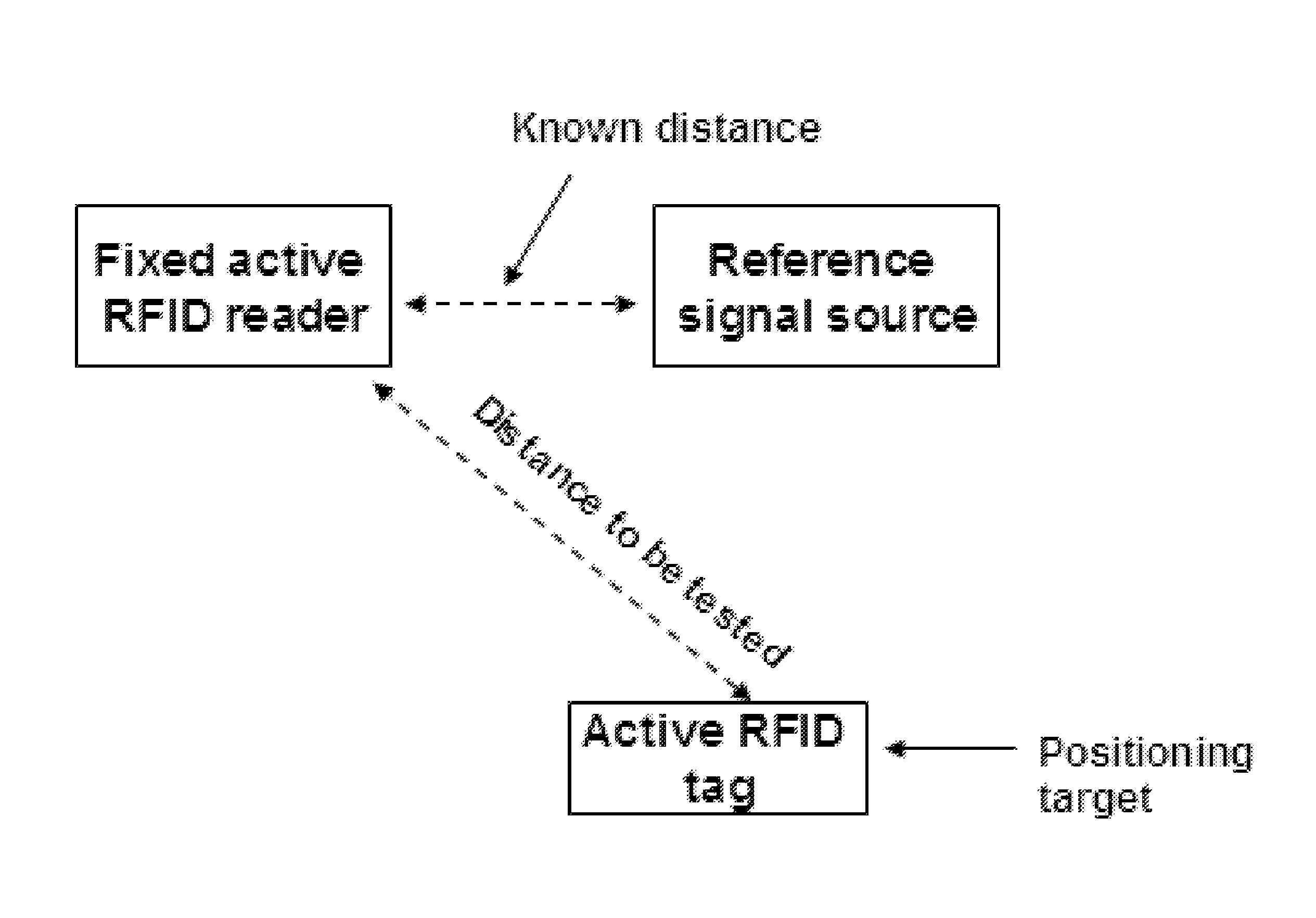
[0125]According to the present invention, the system for positioning the active RFID tag in one dimensional space includes: an active RFID tag, control processor, coordinator, and two active RFID readers, active RFID reader 1 and active RFID reader 2, arranged in straight tunnel.

[0126]Step 1: The coordinator continuously transmits wakeup signals to the active RFID tag on the wakeup channel (channel F1).

[0127]Step 2: The active RFID tag in the standby state receives the wakeup signals on the wakeup channel in the interception time period, and switches to the working channel (channel F2) to transmit the ranging signals to the active RFID tag in the pre-determined ranging signal transmission mode, or transmits the ranging signals according to the information contained in the wakeup signals that is used for controlling the mode for the active RFID tag to transmit ranging signals.

[0128]Step 3: Upon receiving these ranging signals, the active RFID reader calculates the PLR of the ranging ...


PUM


Abstract

A system and method for positioning using signal transmit power, SNR of the signal receiving unit, signal receive PER or PLR, and distance relationship between the signal source and receiving unit. The system includes a ranging signal transmitting unit and receiving unit. The transmitting unit continuously transmits a fixed number of ranging signal packets using different transmit powers, and the receiving unit receives the ranging signal packets, collect statistics for the PLR at each transmit power, and calculates the distance between the transmitting unit and itself using the distance relationship. The present invention uses the reference signal source and the method for calculating relative distance to reduce the impact from the noise and environment changes on the positioning, and introduces the critical transmit power to further enhance positioning precision. With the method provided in the present invention, using a common active RFID tag achieves high precision and effective positioning.

Description

CROSS-REFERENCE TO RELATED APPLICATIONS[0001]This application is a continuation of International Patent Application No. PCT / CN2010 / 070041, with an international filing date of Jan. 6, 2010, designating the United States, now pending, which is based on Chinese Patent Application No. 200910058045.3, filed on Jan. 6, 2009. The contents of these specifications are incorporated herein by reference.BACKGROUND OF THE INVENTION[0002]1. Field of the Invention[0003]The present invention relates to radio frequency technologies, and in particular, to a system and method for positioning using signal transmit power and signal receive packet error rate (PER).[0004]2. Description of the Related Art[0005]The conventional radio frequency positioning technologies, besides commonly used global positioning system (GPS), include radar positioning, radio directional positioning, received signal strength indication (RSSI) positioning, radio frequency signal, time of arrival (TOA), and time difference of ar...

Claims


Application Information

Patent Timeline
Patent Type & Authority Patents(United States)
IPC IPC(8): G01S3/02
CPCH04L12/40013G01S11/06
Inventor LIAO, JASON Y.SUN, CHANGZHENG
Owner WESTVALLEY DIGITAL TECH
Why Eureka
Try Eureka