Fuel injection system with pressure boosting

a fuel injection system and pressure booster technology, applied in the direction of fuel injection apparatus, machine/engine, feed system, etc., can solve the problems of large control quantity that has to be diverted, and large number of components needed for triggering the pressure booster, so as to increase the efficiency of the pressure booster of the fuel injection system

Inactive Publication Date: 2012-08-21
ROBERT BOSCH GMBH
View PDF14 Cites 17 Cited by
  • Summary
  • Abstract
  • Description
  • Claims
  • Application Information

AI Technical Summary

Benefits of technology

[0008]It is the object of the present invention to minimize not only the need for components and installation space but also the control quantity for triggering the pressure booster, in order to increase the efficiency of the pressure boosting of the fuel injection system.
[0009]The fuel injection system of the invention is optimized in terms of the need for installation space for individual system components. Because of a modular construction of the high-pressure pump, pressure booster, high-pressure reservoir and fuel injector, the fuel injection system of the invention can be used in all the known installation spaces of internal combustion engines, such as in the cylinder head region. Because of the disposition of the central hydraulic pressure booster between the high-pressure pump and the high-pressure reservoir (common rail), the central pressure booster has to be triggered only once per injection cycle of a fuel injector. As a result, the control quantity and leak fuel quantity are reduced considerably as a function of the number of injections. Because of this circumstance, the high-pressure pump can also be made smaller, since less fuel has to be pumped, since the number of refilling phases of the control chamber of the central hydraulic pressure booster is reduced considerably. The central pressure booster can as a result be designed in terms of its high-pressure delivery quantity for the maximum possible injection quantity of at least one fuel injector.
[0012]The leak fuel losses that occur by way of the guide gaps, subjected to high pressure, at the pressure booster piston, can be reduced if the central hydraulic pressure booster, whose pressure booster piston is embodied with a first pressure booster piston part with a greater diameter D21 and with a second pressure booster piston part with a lesser diameter D22, is guided by at least one of the pressure booster piston parts in a piston guide body embodied on the base body. The piston guide body is surrounded at least partly by an annular chamber that is part of the hydraulic storage chamber. As a result, at least one pressure booster piston part is likewise surrounded by the pressure in the hydraulic storage chamber. By means of this provision, the guides of the pressure booster piston are subjected from outside at the instant of the pressure boosting to a supporting pressure, so that the guide play spreads less markedly because of the high internal pressure that prevails inside the high-pressure chamber. It is most expedient if the high-pressure chamber with its guide gap for the pressure booster piston is immediately adjacent the hydraulic storage chamber. As a result, the leak fuel loss from the high-pressure chamber into the hydraulic storage chamber, which is at medium pressure, is slight, since the medium pressure is the fuel pressure furnished by the high-pressure pump.

Problems solved by technology

However, the distributor device has no pressure storage function.
A disadvantage of the pressure boosting systems is the high number of components needed as well as the relatively large control quantity for triggering the pressure booster.
The result is a large control quantity that has to be diverted and that must accordingly be counted as a lost quantity in the injection system.
Moreover, with increasing injection pressures, the lost quantity increases in proportion to the fourth power across the gap width in the guide of the pressure booster piston, and this adversely affects the hydraulic efficiency of such fuel injectors.

Method used


Image

  • Fuel injection system with pressure boosting
  • Fuel injection system with pressure boosting
  • Fuel injection system with pressure boosting

Examples


Embodiment Construction

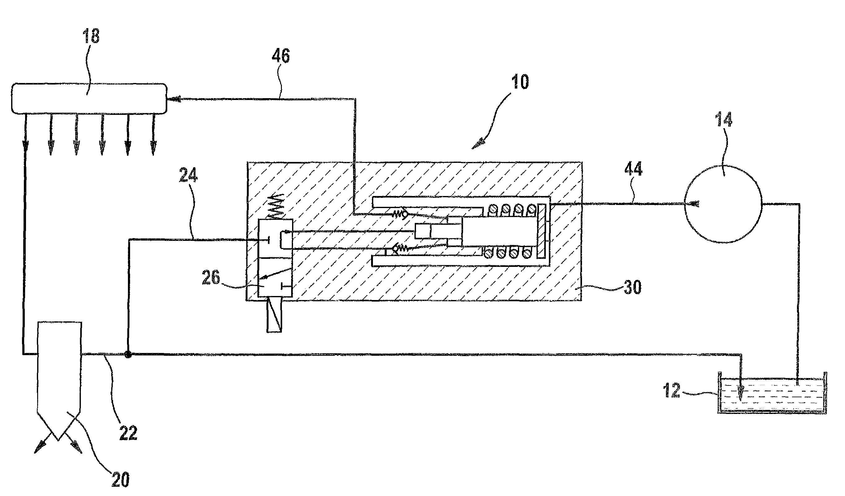
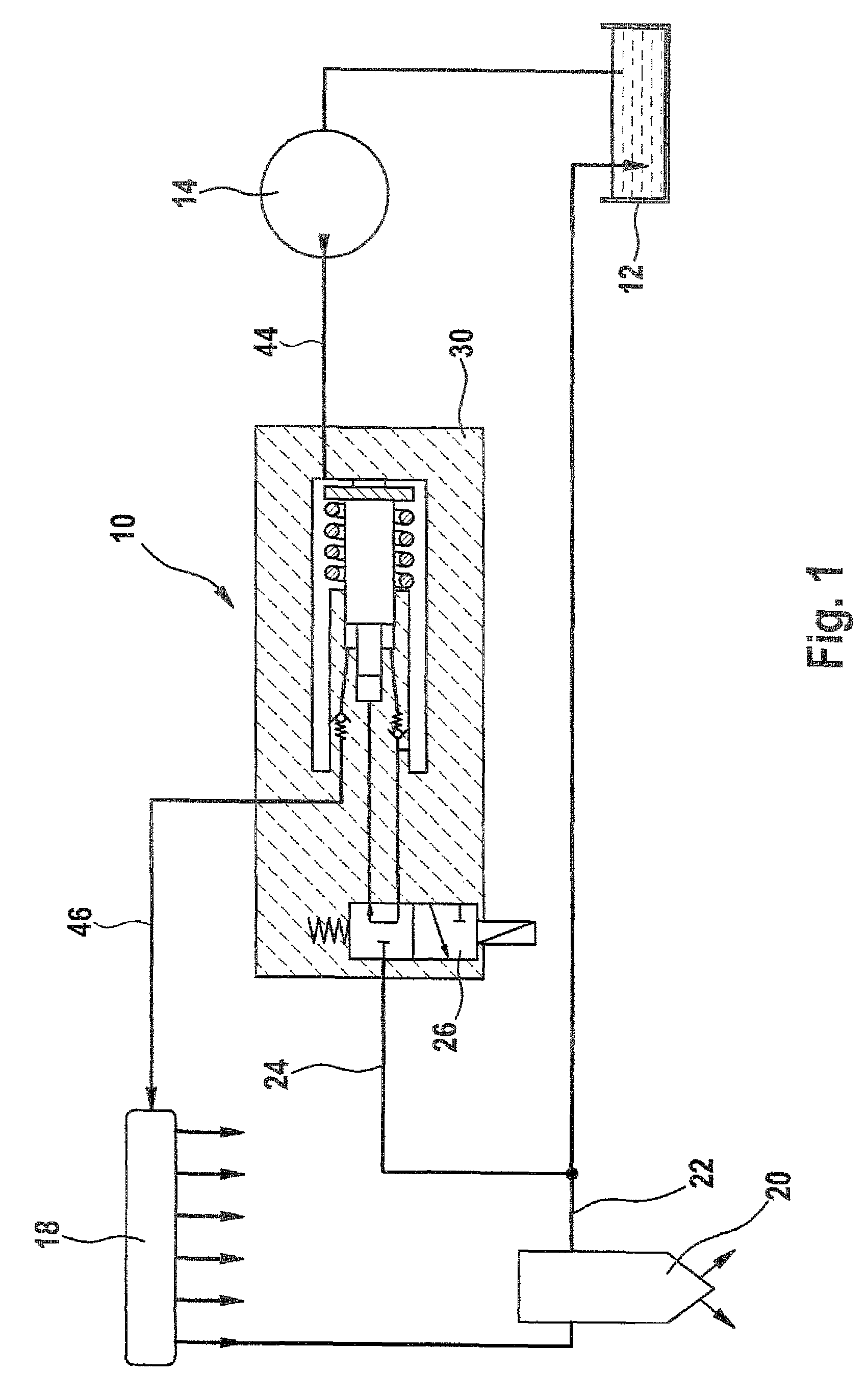
[0019]The fuel injection system shown in FIG. 1 includes a fuel tank 12, from which fuel is pumped via a high-pressure pump 14 and delivered to a central hydraulic pressure booster 10. The central pressure booster 10 communicates on one side with the aforementioned high-pressure pump 14 via a pressure booster inlet 44, and on the other side, it acts on a high-pressure reservoir 18 (common rail). Connection lines to fuel injectors 20, the injectors being indicated only schematically in the view in FIG. 1, are located in the high-pressure reservoir 18 and correspond in number to the fuel injectors that are to be supplied with fuel at system pressure. On the combustion end of the fuel injectors, the fuel—represented by the arrows—at high pressure is injected into the combustion chamber of a self-igniting internal combustion engine. On the return side of the fuel injector 20 there is an injector return 22, into which a pressure booster return 24, which is connected to a switching valve ...


PUM


Abstract

The invention relates to a fuel injection system for an internal combustion engine having a high pressure pump, a high pressure reservoir, a plurality of fuel injectors, a hydraulic pressure booster, and a control valve for actuating the hydraulic pressure booster. The hydraulic pressure booster is provided centrally for all of the fuel injectors. The central hydraulic pressure booster is disposed between the high pressure pump and the high pressure reservoir.

Description

CROSS-REFERENCE TO RELATED APPLICATION[0001]This application is a 35 USC 371 application of PCT / EP2008 / 054464 filed on Apr. 14, 2008.BACKGROUND OF THE INVENTION[0002]1. Field of the Invention[0003]The invention relates to a fuel injection system with pressure boosting for internal combustion engines.[0004]2. Description of the Prior Art[0005]A fuel injection system with pressure boosting, in which a central hydraulic pressure booster is provided for all the fuel injectors, is known from European Patent Disclosure EP 1 125 046 B1. The fuel pumped by means of a high-pressure pump is delivered to a central pressure reservoir (first common rail). The central pressure booster is connected downstream of the central pressure reservoir in the delivery direction of the fuel and delivers the pressure-boosted fuel to a further pressure reservoir (second common rail), from which a plurality of pressure lines corresponding to the number of injectors lead away the individual fuel injectors.[0006]...

Claims


Application Information

Patent Timeline
Patent Type & Authority Patents(United States)
IPC IPC(8): F02M37/00
CPCF02M47/027F02M57/025F02M59/105F02M63/0225
Inventor KUHNKE, DOMINIKVAHLE, DIRK
Owner ROBERT BOSCH GMBH
Why Eureka
Try Eureka