

Automatic analyzer
a technology of automatic analyzer and analyzer, which is applied in the direction of material analysis, chemical methods analysis, instruments, etc., can solve the problems of abnormal measurement, large time required to determine the cause of abnormality in the conventional analyzer, and the function of the conventional automatic analyzer
- Summary
- Abstract
- Description
- Claims
- Application Information
AI Technical Summary
Benefits of technology
Problems solved by technology
Method used
Image

Examples
first embodiment
[0029]A trouble due to a consumable member used in common to measure at least two objects is explicitly notified to a user, who is then encouraged to take countermeasures.
[0030]An example is described by using a system reagent with reference to FIG. 3.
[0031]First, reagents are registered in step S1. A handy barcode reader is attached on the analyzer so that lot information of system reagents can be easily registered. Alternatively, identifiers (μ chips or IC tags) are embedded in consumables, information thereon is read wirelessly, and system reagent information is registered in the analyzer. In order to limit item reagents, 1) a standard range of a general sample in each item is input; and 2) an expected value (desired value) of each sample (Control-Calibration) is input. Then, lot information is recorded or stored. Information about consumables used in common to measure at least two objects is stored by item, measurement condition, and time, and the information is stored in the an...
second embodiment
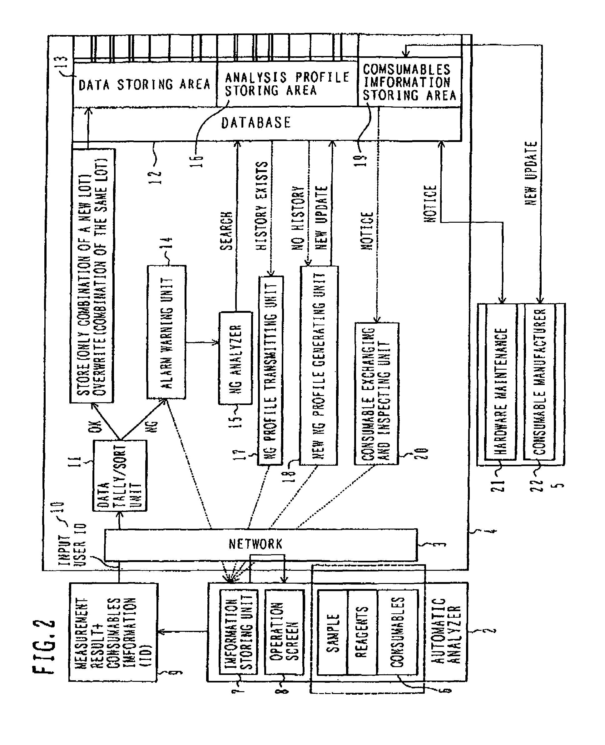
[0038]Hereinafter, the definition of the data service center in the present invention is described with reference to FIG. 2.
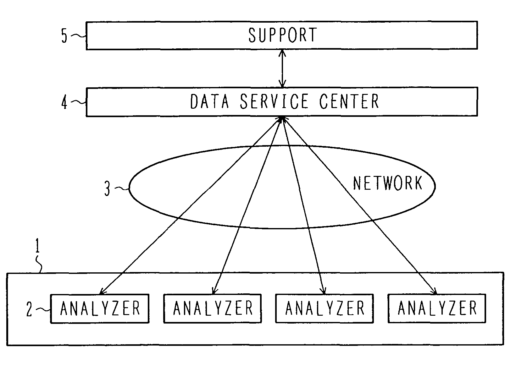
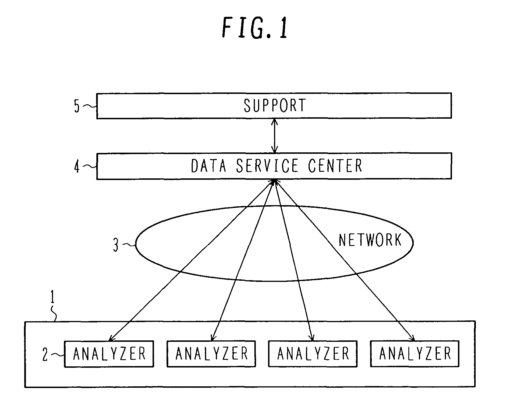
[0039]The data service center 4 connects to a plurality of analyzers 2 through a network 3 and serves as an agency to store measurement results in the respective analyzers and information about the consumables used. The center 4 is provided with the database 12 to accumulate the information 9 including the measurement results obtained from the analyzers 2 and ID information of the consumables used. The database 12 receives the information from each of the analyzers 2. The information received by the database is stored in units of users. Also, the information is stored while being sorted by analyzer, analysis item, and information about consumables. A user can access history information by inputting his / her user ID in the user ID authenticating unit 10. Also, an average of measurement values received from the automatic analyzers 2 is calculated, measurement resu...
third embodiment
[0040]A method for identifying and determining consumables at data failure is described with reference to FIG. 4.
[0041]In step S1, the information 9 including measurement results associated with the name of an item, an expected value, an actual value, and consumables, is transmitted from an inspection facility 1 to the data service center 4 through the network 3.
[0042]In step S2, the database 12 in the center 4 receives the information 9 from the analyzers in each inspection facility.
[0043]In step S3, the measurement results and information about consumables are accumulated in the database 12 in the center 4.
[0044]In step S4, a common point in the plurality of analyzers is searched for and is analyzed.
[0045]In step S5, countermeasures are taken on the basis of the information found in step S3.
[0046]In step S6, the center 4 transmits the countermeasures and warning to the analyzers 2. In step S7, history information stored in the data storing area 13 in the center 4 is browsed.
[0047]...
PUM
| Property | Measurement | Unit |
|---|---|---|
| constant temperature | aaaaa | aaaaa |
| time | aaaaa | aaaaa |
| wavelength | aaaaa | aaaaa |
Abstract
Description
Claims
Application Information