Method for determining a location from images acquired of an environment with an omni-directional camera

a technology of omni-directional camera and image acquisition, applied in the field of determining a location from images acquired of an environment with an omni-directional camera, can solve the problems of difficult to access, difficult to locate, and obstructed signals by buildings, so as to improve the accuracy of location and orientation estimation, the effect of easy access

Inactive Publication Date: 2012-08-21
MITSUBISHI ELECTRIC RES LAB INC
View PDF4 Cites 14 Cited by
  • Summary
  • Abstract
  • Description
  • Claims
  • Application Information

AI Technical Summary

Benefits of technology

[0010]In the urban setting, the skyline is generally unique when observed from a particular viewpoint, i.e., location and orientation. Therefore, the method extracts the skyline from the image and compares the extracted skyline to synthetic skylines in virtual omni-directional images synthesized from the 3D model. By matching the skylines, localization with sub-meter accuracy can be achieved, which can be much better than GPS localization, particularly in an urban setting.
[0012]The method can take advantage of photorealistic building details in the texture of images to enhance the precision of the location and orientation estimates; whereas IR cameras cannot image such details.
[0013]The embodiments of the invention can easily access these models using wireless communication links, and synthesize the virtual images in real time to provide location techniques for vehicles, or anyone carrying a single omni-directional camera equipped with a processor to perform the steps of the method.

Problems solved by technology

Unfortunately, GPS has limitations because the signals are broadcasted at 500 watts from satellites about 12,000 miles up.
The signals can be obstructed by buildings, and even foliage.
This is called the urban canyon problem.
Pose estimation, although extremely challenging due to several degeneracy problems and inaccurate feature matching, is well known in computer vision.
However, most conventional solutions are only proven on a small scale, typically in a well controlled environment.
That system requires an expensive infrared camera, which makes it impractical for large-scale deployment in consumer oriented applications, such as vehicle or hand-held devices.
As a result, their approach can lead to potential inaccuracies when the camera is not vertically aligned.
That makes it a challenge to determine a technique for capturing images of cyclical patterns used in camera calibration.

Method used


Image

  • Method for determining a location from images acquired of an environment with an omni-directional camera
  • Method for determining a location from images acquired of an environment with an omni-directional camera
  • Method for determining a location from images acquired of an environment with an omni-directional camera

Examples


Embodiment Construction

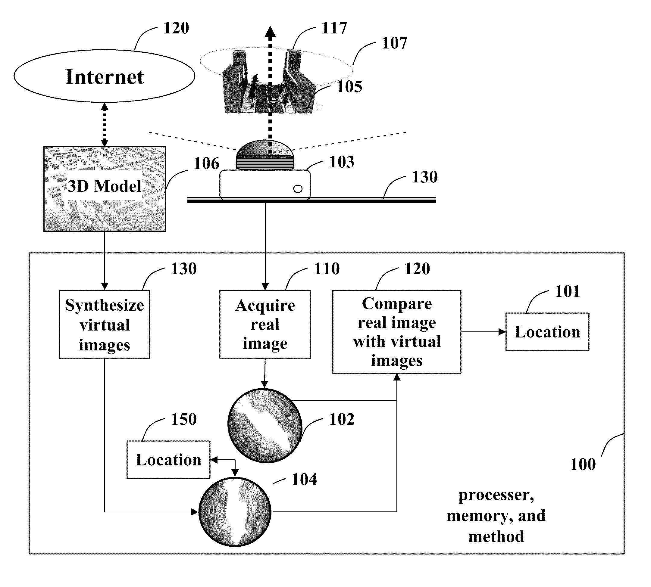
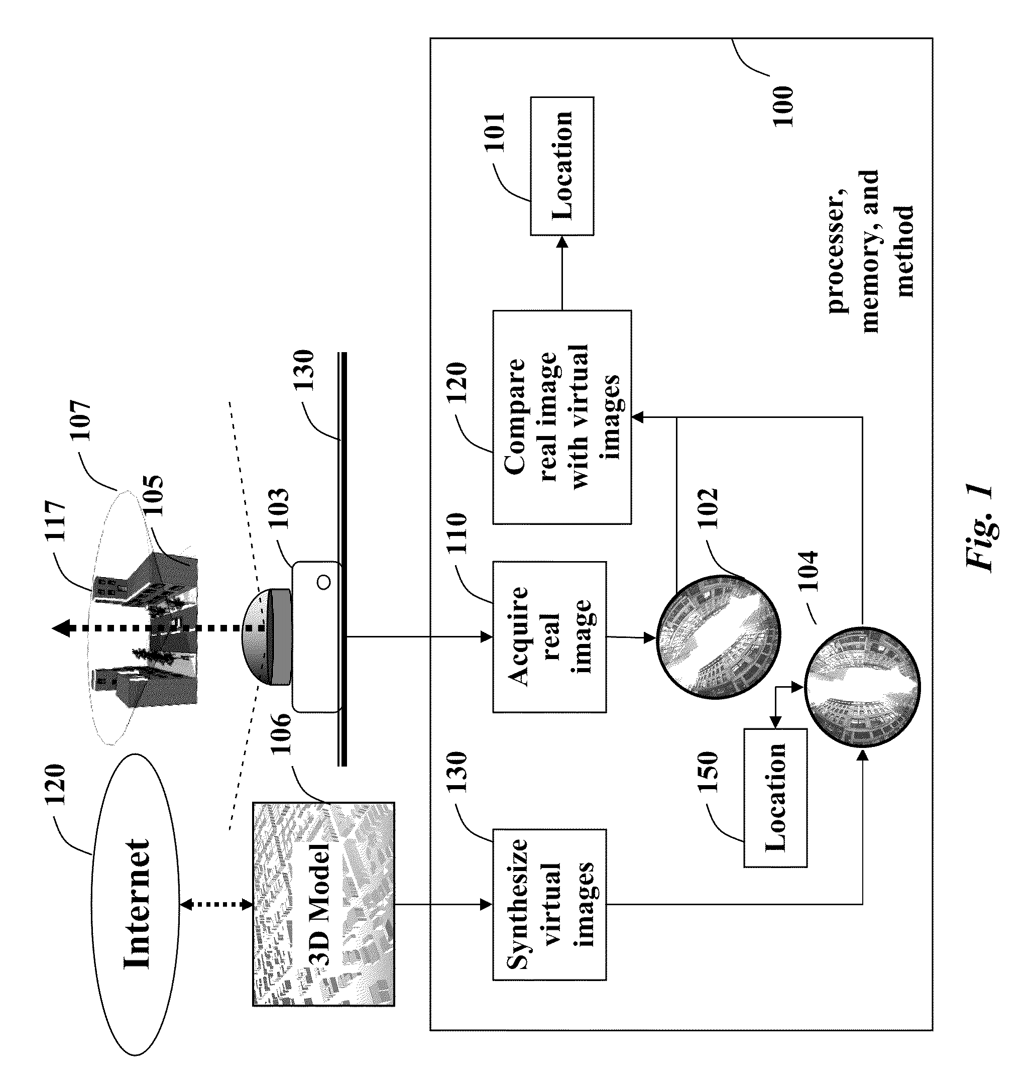
[0023]As shown in FIG. 1, embodiments of our invention provide a method and system 100 for determining a 6D location and orientation 101 in an environment 105 from a real omni-directional image 102 acquired 110 of a skyline 106 in the environment with an omni-directional visible light camera 103 at an unknown location and orientation. The optical axis 117 of the camera is oriented substantially vertical to a ground plane, which may be planar or not. The camera acquires images of the skyline in the environment. The camera can be mounted in a vehicle, or the user of the camera can just simply place the camera back on the ground plane 130.

[0024]The real image 102 is compared 120 with virtual omni-directional images 104 synthesized 130 from a 3D model 106 of the environment for known locations and orientations. The 3D model can be acquired in real-time using the Internet 120 or the 3D model can be stored in a memory of the system.
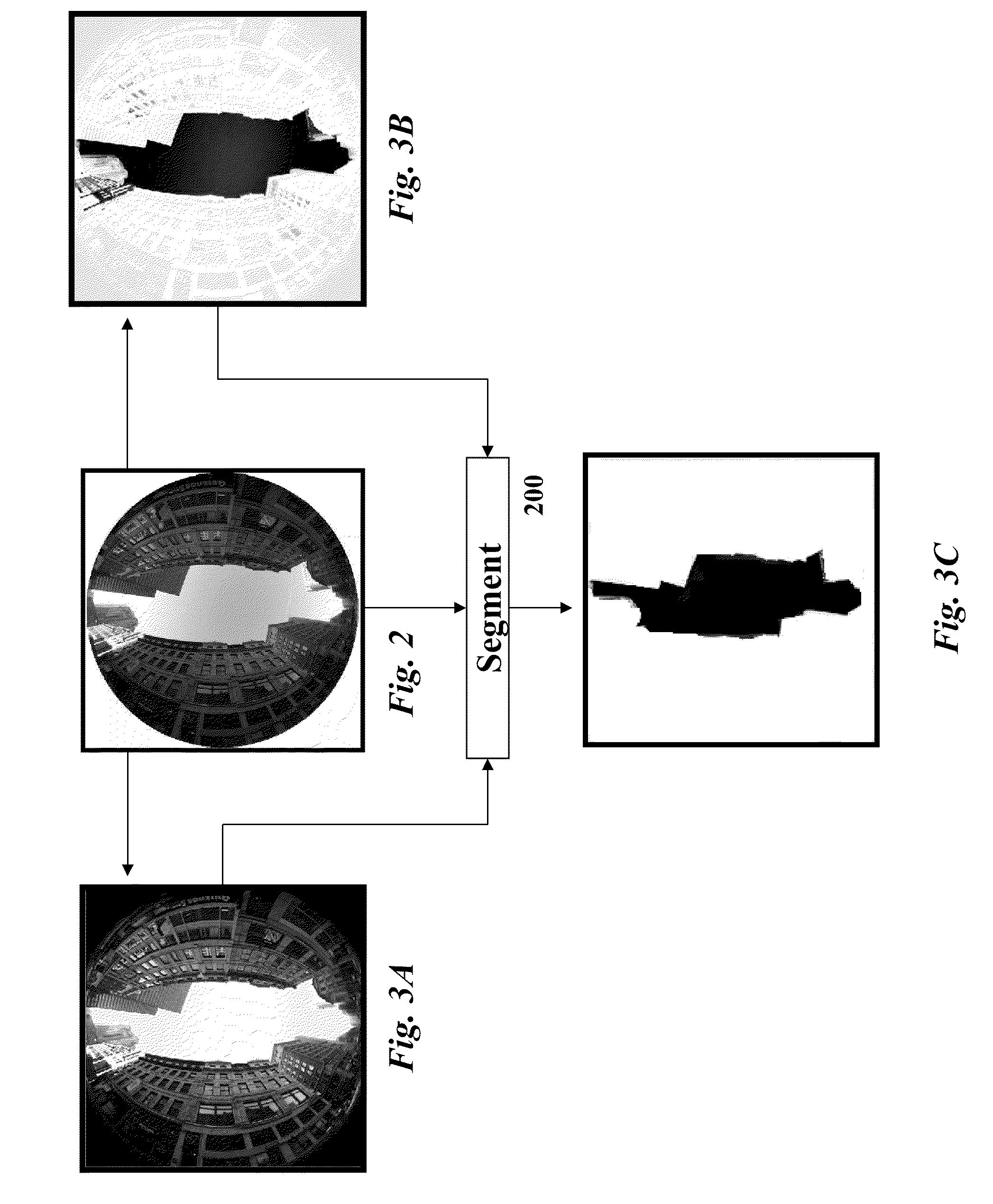
[0025]Sky Detection

[0026]As shown in FIG. 2, the real ima...


PUM


Abstract

A location and orientation in an environment is determined by first acquiring a real omni-directional image of an unknown skyline in the environment. A set of virtual omni-directional images of known skylines are synthesized from a 3D model of the environment, wherein each virtual omni-directional image is associated with a known location and orientation. The real omni-directional image with each virtual omni-directional images to determine a best matching virtual omni-directional image with the associated known location and orientation.

Description

BACKGROUND OF THE INVENTION[0001]It is often desired to determine one's location, for example when driving. One way to do this is to use a global positioning system (GPS). Unfortunately, GPS has limitations because the signals are broadcasted at 500 watts from satellites about 12,000 miles up. Signals from four satellites are required for normal operation. The signals can be obstructed by buildings, and even foliage. This is called the urban canyon problem. In mobile automotive GPS receivers, metallic features in windshields, such as defrosters, or window tinting films can act as a Faraday cage, further degrading reception.[0002]Therefore, it is desired to use computer vision techniques. In computer vision applications, images are analyzed to determine poses, i.e., location and orientation. Pose estimation, although extremely challenging due to several degeneracy problems and inaccurate feature matching, is well known in computer vision. However, most conventional solutions are only...

Claims


Application Information

Patent Timeline
Patent Type & Authority Patents(United States)
IPC IPC(8): G06K9/00
CPCG01C21/3602G06K9/00208G06K9/00704G06T7/0018G06T7/0093G06T2207/20016G06T2207/20144G06T2207/30244G06T7/80G06T7/162G06T7/194G06V20/647G06V20/39
Inventor RAMALINGAM, SRIKUMARBRAND, MATTHEWBOUAZIZ, SOFIEN
Owner MITSUBISHI ELECTRIC RES LAB INC
Why Eureka
Try Eureka