Fusing apparatus for high speed electrophotography system

a high-speed electrophotography and fuser technology, applied in the field of printing, can solve the problems of excessive toner offset, fuser roller may not have returned to working temperature, and degradation of the throughput rate of the receiver, so as to improve the efficiency and accuracy of the release system, and improve the control release of the receiver

Active Publication Date: 2012-08-21
EASTMAN KODAK CO
View PDF15 Cites 70 Cited by
  • Summary
  • Abstract
  • Description
  • Claims
  • Application Information

AI Technical Summary

Benefits of technology

[0023]In accordance with an object of the invention, both a system and a method are provided for improving the controlled release of a receiver in conjunction with a fuser in a printing system, and specifically the efficiency and accuracy of the release system. One embodiment of this method includes a belt fuser that allows the separating of the heat transfer and release functions of the fuser such that fuser roller could be made of hard metal core that can be heated to high temperatures without the fear of delaminating elastomeric coatings which are common in roller fusing. The release is achieved by bending the fuser belt around a smaller release roller after the fuser nip between the rollers. Media stiffness will make the media to separate from the belt at a sharp bend at roller. Furthermore additional heat can be provided by an external heat source such as heated roller.

Problems solved by technology

Higher or lower temperatures can cause excessive toner offset (i.e., toner powder transfer to the fuser roller) in roller fusers.
If the receivers are presented at a too-rapid rate, the fuser roller may not have returned to its working temperature when the next receiver arrives.
Consequently, the receivers must be stopped or slowed until the temperature of the fuser roller has come within acceptable range and such stopping or slowing results in degradation of receiver throughput rate.
The change of fuser temperature and / or reduction of speed results in reduced productivity.
Furthermore, if different receiver types are required in a single document, extra time is needed to collate images on different receivers into the document.
The receiver released is often a problem in high speed printers.
These methods have disadvantages for example the contact skives can leave streaking artifacts on the image and air skives require a large supply of forced air.
The main drawback of these methods is that a roller fuser configuration that has an elastomer layer on the fuser roller forms a nip that effectively acts as a thermal barrier.
This creates a situation where the media separation from the fuser roller surface becomes more difficult.
Unfortunately often improving the heat transfer deteriorates the media release from the fusing surface of internally heated roller fusers.
Most commonly with heated metal rollers, high-speed printing creates a difficult problem because the high temperature and high stress employed by the heating rollers to the top soft release layer of the fuser roller may reduce its useful life.
One of these problems is supplying enough heat to fuse an image in the higher speed printers.

Method used


Image

  • Fusing apparatus for high speed electrophotography system
  • Fusing apparatus for high speed electrophotography system
  • Fusing apparatus for high speed electrophotography system

Examples


Embodiment Construction

[0032]The present description will be directed in particular to elements forming part of, or cooperating more directly with, apparatus and methods in accordance with the present invention. It is to be understood that elements not specifically shown or described may take various forms well known to those skilled in the art.

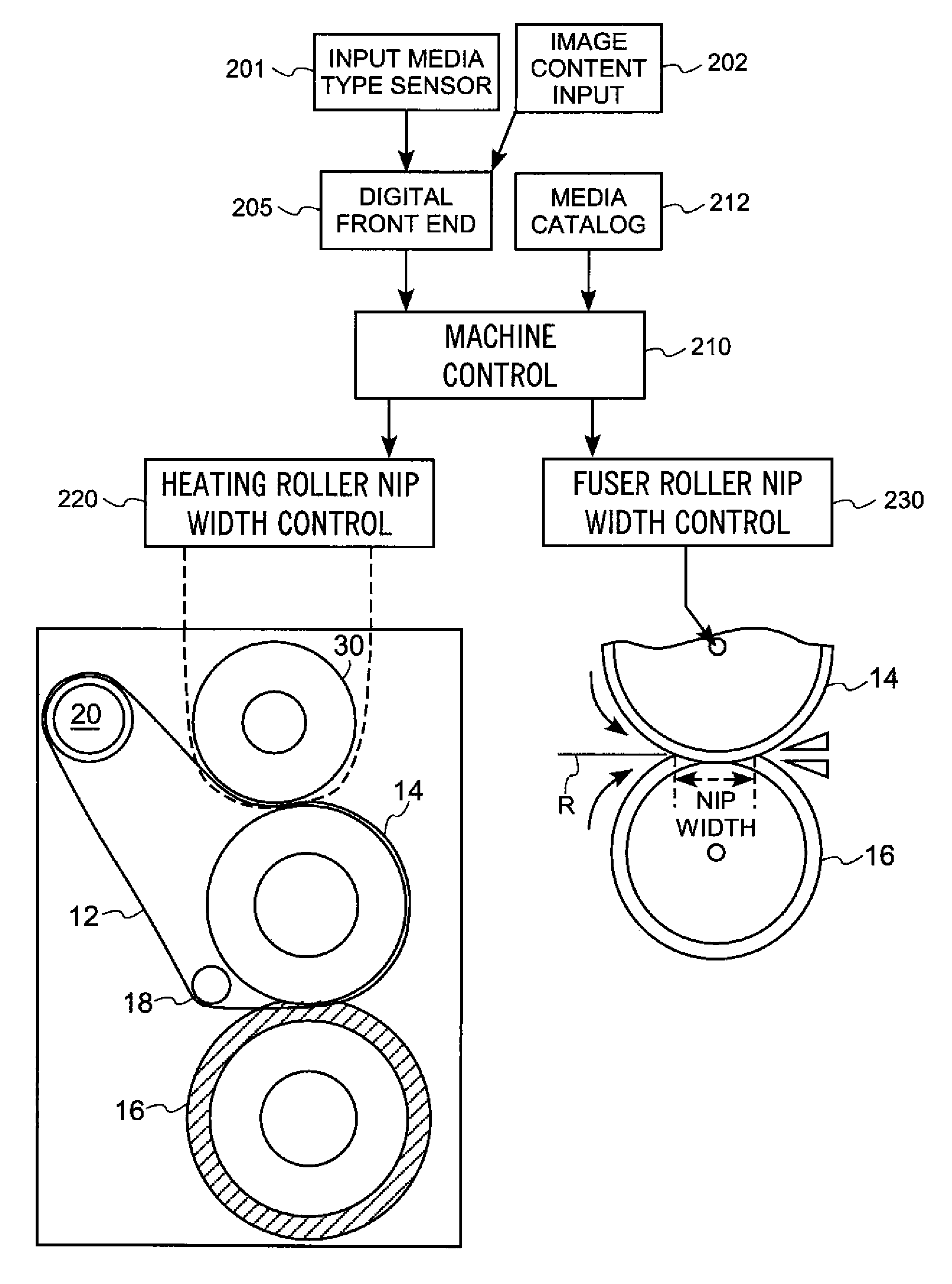
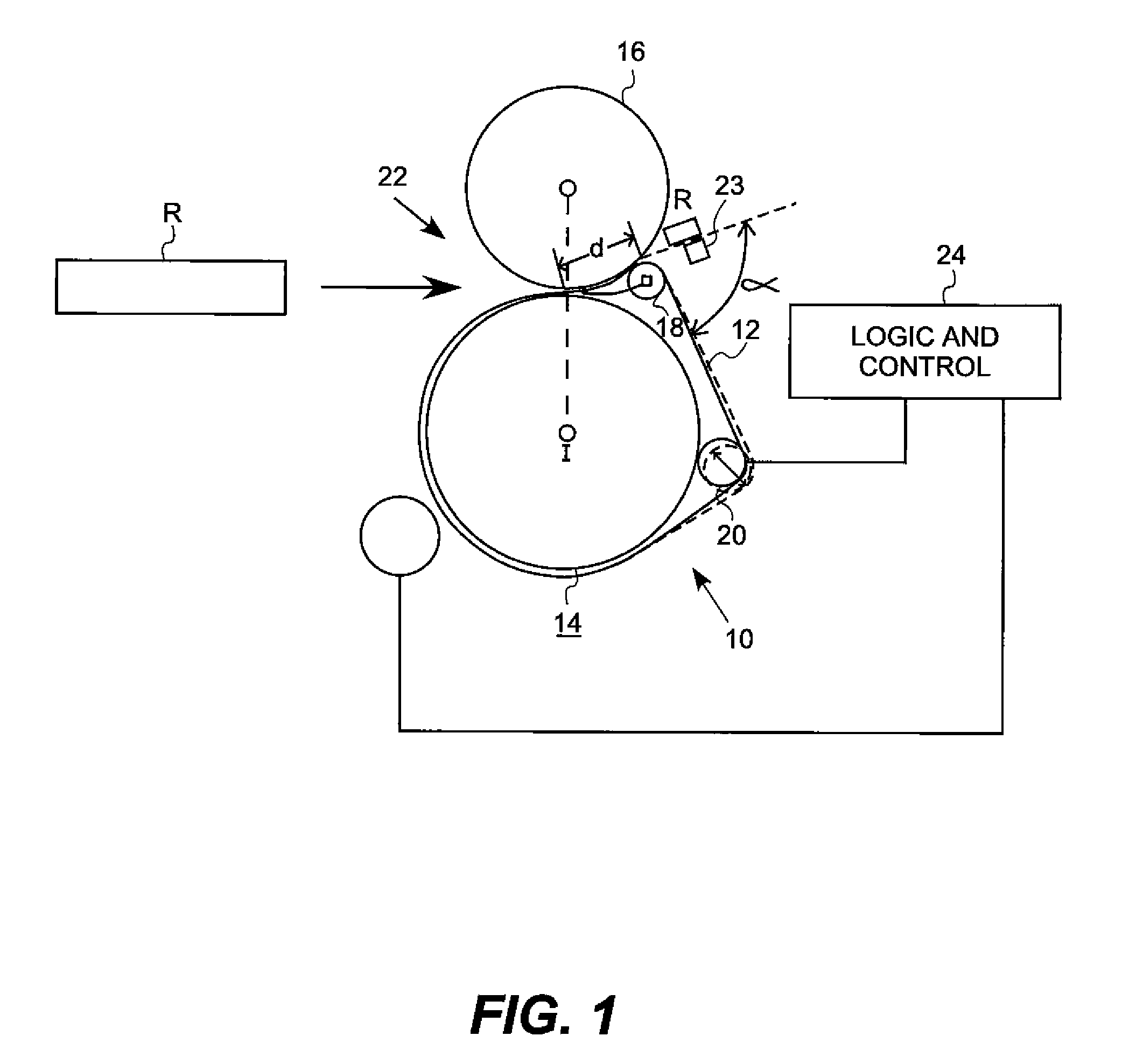
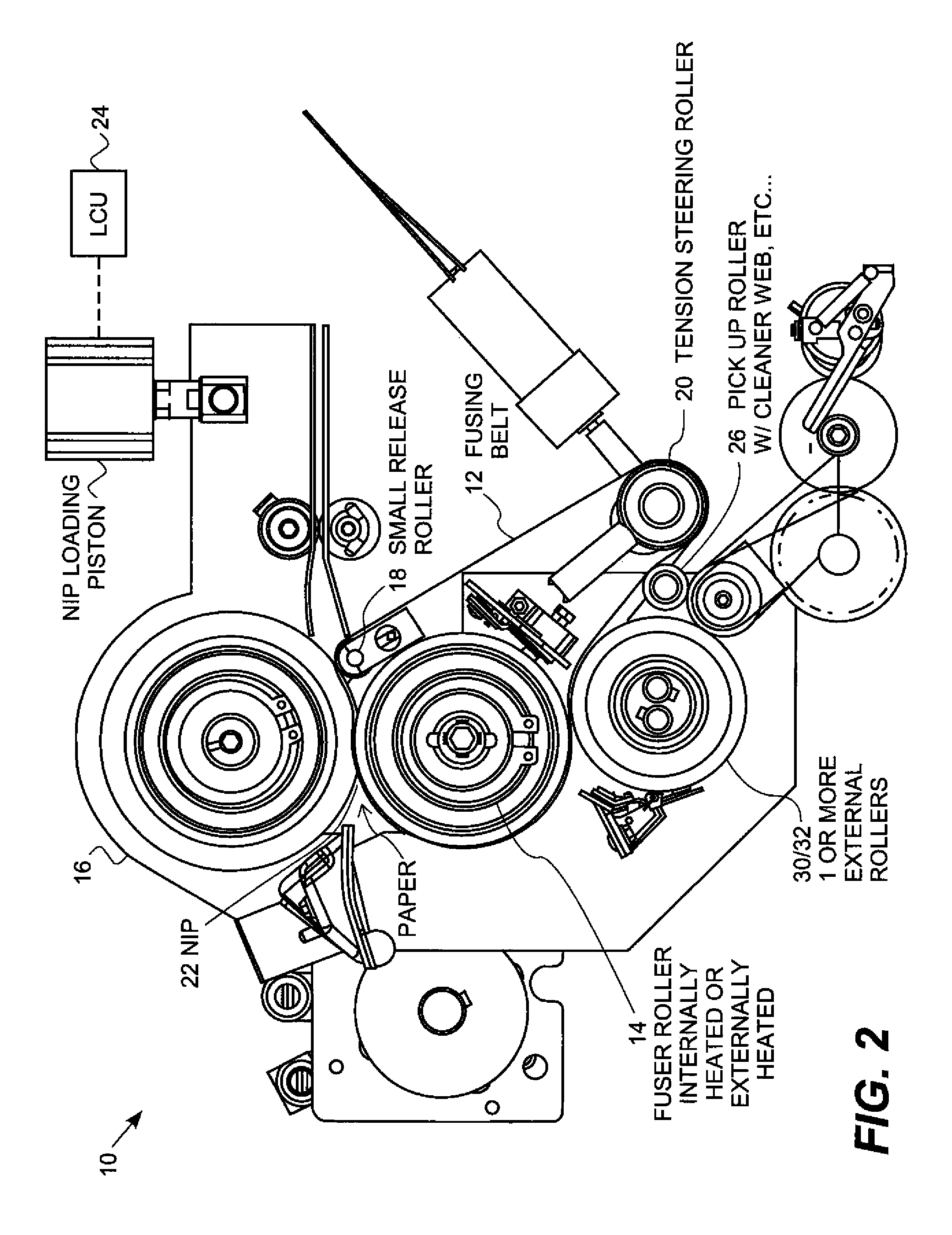
[0033]Various aspects of the invention are presented in FIGS. 1-4 which are not drawn to scale and in which like components are numbered alike. According to one aspect of the invention, the thermal response of the fuser with sheets being fed through the fuser is simulated in the fuser prior to feeding sheets through the fuser. The thermal response may be simulated in a manner that minimizes thermal droop, or it may be simulated in a manner that maintains a nip force, or it may be simulated in a manner that accomplishes both. According to a further aspect of the invention, the thermal response of the fuser with sheets being fed through the fuser is controlled to mai...


PUM


Abstract

A fuser and receiver release system and method are provided for improving the release of receivers in high speed of printing systems. This system controls the release of a receiver in conjunction with a fuser in a printing system, and specifically the efficiency and accuracy of the release system. One embodiment of this method includes a belt fuser that allows the separating of the heat transfer and release functions of the fuser such that fuser roller could be made of hard metal core that can be heated to high temperatures without the fear of delaminating elastomeric coatings which are common in roller fusing.

Description

FIELD OF THE INVENTION[0001]The invention relates generally to the field of printing, and more particularly to processes and apparatus for maintaining quality in digital reproduction systems by controlling the fuser used in the electrostatographic printing process.BACKGROUND OF THE INVENTION[0002]In electrostatographic imaging and recording processes such as electrophotographic reproduction, an electrostatic latent image is formed on a primary image-forming member such as a photoconductive surface and is developed with a thermoplastic toner powder to form a toner image. The toner image is thereafter transferred to a receiver, e.g., a sheet of paper or plastic, and the toner image is subsequently fused to the receiver in a fusing station using heat or pressure, or both heat and pressure. The fuser station can include a roller, belt, or any surface having a suitable shape for fixing thermoplastic toner powder to the receiver.[0003]The fusing step in a roller fuser commonly consists of...

Claims


Application Information

Patent Timeline
Patent Type & Authority Patents(United States)
IPC IPC(8): G03G15/20
CPCG03G15/205G03G15/2039G03G15/2028G03G15/2064G03G2215/0081G03G2215/2032G03G2215/00805
Inventor ASLAM, MUHAMMEDSHIFLEY, JAMES D.BOBO, ROBERT D.
Owner EASTMAN KODAK CO
Why Eureka
Try Eureka