Hermetically sealed wet electrolytic capacitor
a technology of wet electrolytic capacitors and sealed casings, which is applied in the direction of hermetically sealed casings, electrical apparatus casings/cabinets/drawers, casings/cabinets/drawers details, etc., can solve the problems of liquid electrolyte corroding the hermetic seal itself, leakage around conventional non-hermetic polymeric seals,
- Summary
- Abstract
- Description
- Claims
- Application Information
AI Technical Summary
Benefits of technology
Problems solved by technology
Method used
Image
Examples
example 1
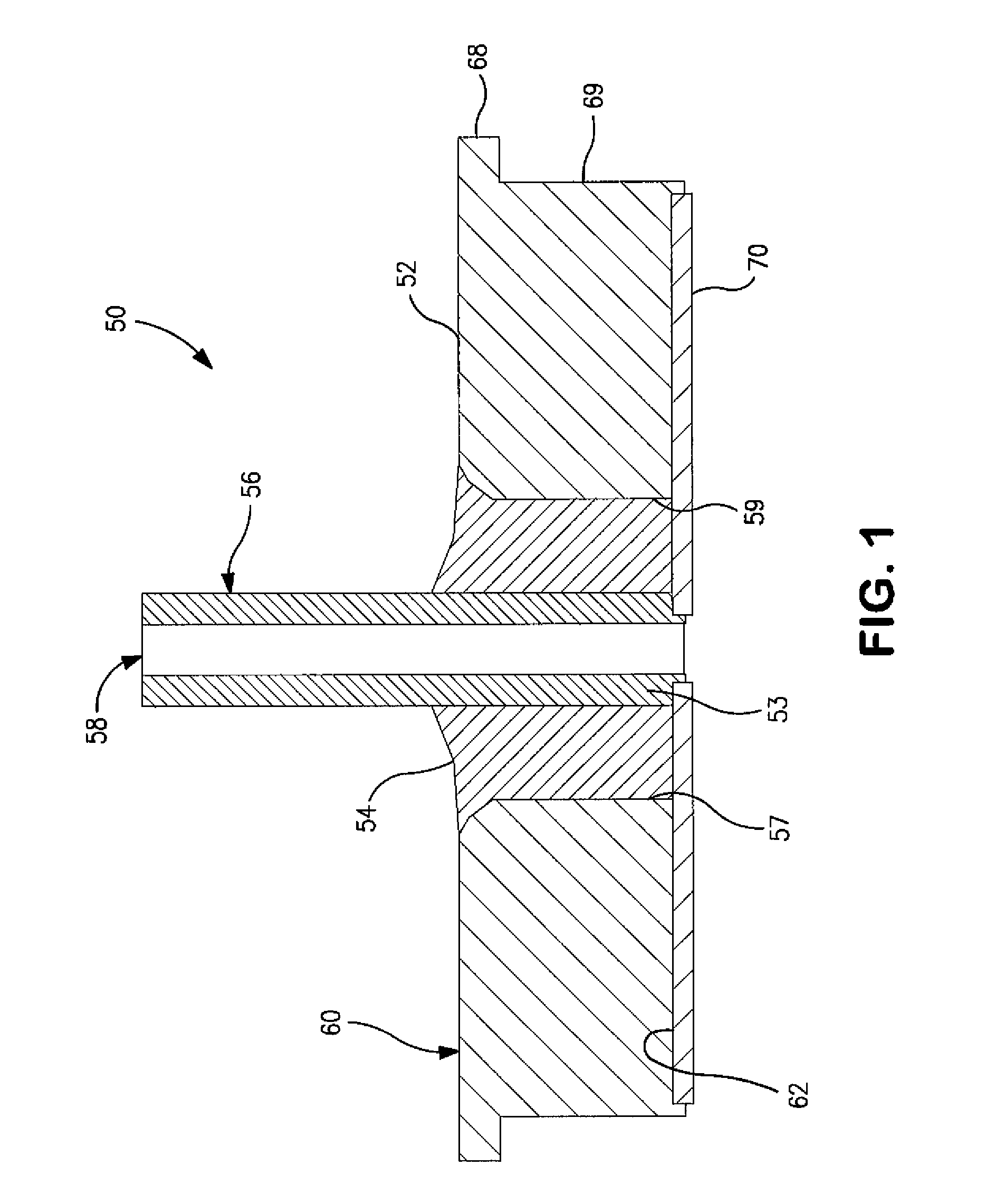
[0070]A wet electrolytic capacitor was formed in accordance with the present invention. A liquid seal was initially formed in the manner shown in FIGS. 7-8. More particularly, a glass-to-metal seal 300a was threaded onto a wire 320 through a tantalum tube 322, with the top of the tube resting against a bead 380 at the end of the wire. A first perform 350a containing a PFA layer 360 and a PTFE layer 362 (obtained from Electrolock) was then positioned over the wire 320 and on the seal 300, with the PFA layer 360 against the seal 300a. Another preform 350b was also placed on the wire 320 such that the PTFA layers of each preform mated together. A second glass-metal seal 300b was threaded onto the wire 320, upside down relative to the first. Additional pairs were positioned in the same way until a manageable stack was obtained. A weight 370 (25-50 grams) was attached to the wire 320, and the entire assembly was then placed in an oven using a fork-like support 373 on the bottom of the st...
example 2
[0072]A wet electrolytic capacitor was formed in accordance with the present invention. A liquid seal was initially formed in the manner shown in FIGS. 9-10. More particularly, a glass-to-metal seal 400 was threaded onto a wire through a tantalum tube. A preform 450 containing a PFA layer 460, PTFE layer 462, and PFA layer 464 (obtained from Electrolock) was then positioned over the wire 420 and on the seal 400, with the PFA layer 460 against the seal 400. A weight 470 (10 grams) was attached to the wire 420, and the entire assembly was then placed in an oven. The oven was raised to 330° C. and held for a period of 15 to 30 minutes, at which time the oven is turned off. When cooled, the stack was removed and disassembled such that the individual seals were accessible and contained a fluorocarbon disk laminated to the tantalum-glass-metal portion. The resulting seal was then assembled with a tantalum anode 480, metal casing (not shown), and electrolyte in the manner described in Exam...
example 3
[0073]A wet electrolytic capacitor was formed in accordance with the present invention. As shown in FIG. 11, a disk of a single PFA layer 550 was threaded onto a formed anode riser wire 542, and then the anode riser wire was inserted into the tube 556. The seal 500, disk 550, and anode 580 were then placed in an oven at 333° C. upside down, so the weight of the anode compressed the PFA disk. The assembly was held at temperature for ½ hour, and then cooled. The assembly was then placed into a metal case 512, into which an amount of electrolyte had been introduced, and a Teflon support 555 had been placed. The seal was pressed into the can, and the circumference welded. The center tube was sealed with a laser, and the leads attached in the manner known to the art.
PUM
 Abstract
Description
Claims
Application Information
 - R&D
- Intellectual Property
- Life Sciences
- Materials
- Tech Scout
- Unparalleled Data Quality
- Higher Quality Content
- 60% Fewer Hallucinations
Browse by: Latest US Patents, China's latest patents, Technical Efficacy Thesaurus, Application Domain, Technology Topic, Popular Technical Reports.
© 2025 PatSnap. All rights reserved.Legal|Privacy policy|Modern Slavery Act Transparency Statement|Sitemap|About US| Contact US: help@patsnap.com


