Apparatus and method for endoscopic 3D data collection

a technology of endoscopic 3d and apparatus, applied in the field of apparatus for can solve the problems of affecting the accuracy of endoscopic 3d data collection,

Active Publication Date: 2012-09-11
STORZ ENDOSKOP PROD GMBH
View PDF22 Cites 51 Cited by
  • Summary
  • Abstract
  • Description
  • Claims
  • Application Information

AI Technical Summary

Benefits of technology

[0009]Continual modulation of the measuring beam can be produced with relatively simple electronic means, and phase-sensitive solid body sensors are available that are of simple construction, easy to operate, and reasonably priced. Time delays, which correspond to differences in depth in the mm range of more than several meters, can be easily and reliably demonstrated with a corresponding frequency modulation. It is the pixel-triggered collection and evaluation of the phase information that makes possible the production of an image that depicts locally triggered depth and distance information. Thanks to the addition of the image of any desired additional image sensor, even one with different format, it is possible to have a simple and secure orientation in the 3D image as well as to obtain additional information, such as spectrally selected or triggered data.
[0044]Likewise, to generate a broadband illumination, fiber-pumped fluorescent light sources, such as is disclosed for instance in US 20070092184 A1, can be used, if they comprise sufficiently brief fluorescent lifetime. Using supercontinuum white light laser sources has the additional advantage that they can be modulated, possibly synchronously with the phase-sensitive image sensor. In addition, supercontinuum white light lasers can radiate wavelength-selectively and accordingly can be powered electrically. Such a light source can suffice for generating all necessary types of beam.

Problems solved by technology

Methods of this type are relatively robust, but the precision depends decisively on the triangulation base, which is always closely limited in endoscopic applications.
In addition, these methods must make do with relatively few data points.

Method used


Image

  • Apparatus and method for endoscopic 3D data collection
  • Apparatus and method for endoscopic 3D data collection
  • Apparatus and method for endoscopic 3D data collection

Examples


Embodiment Construction

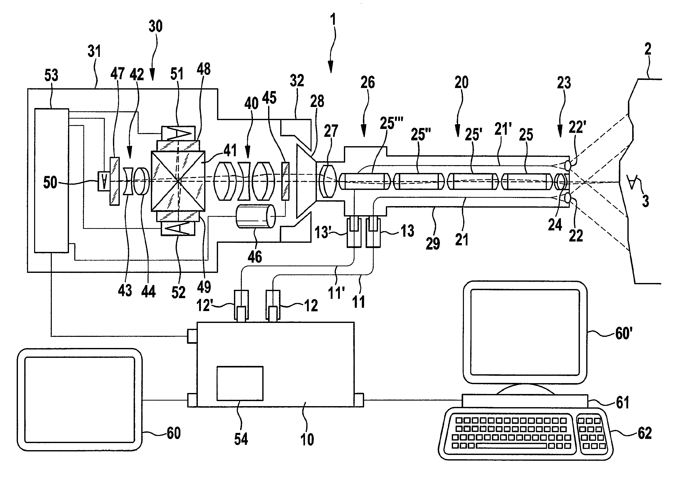
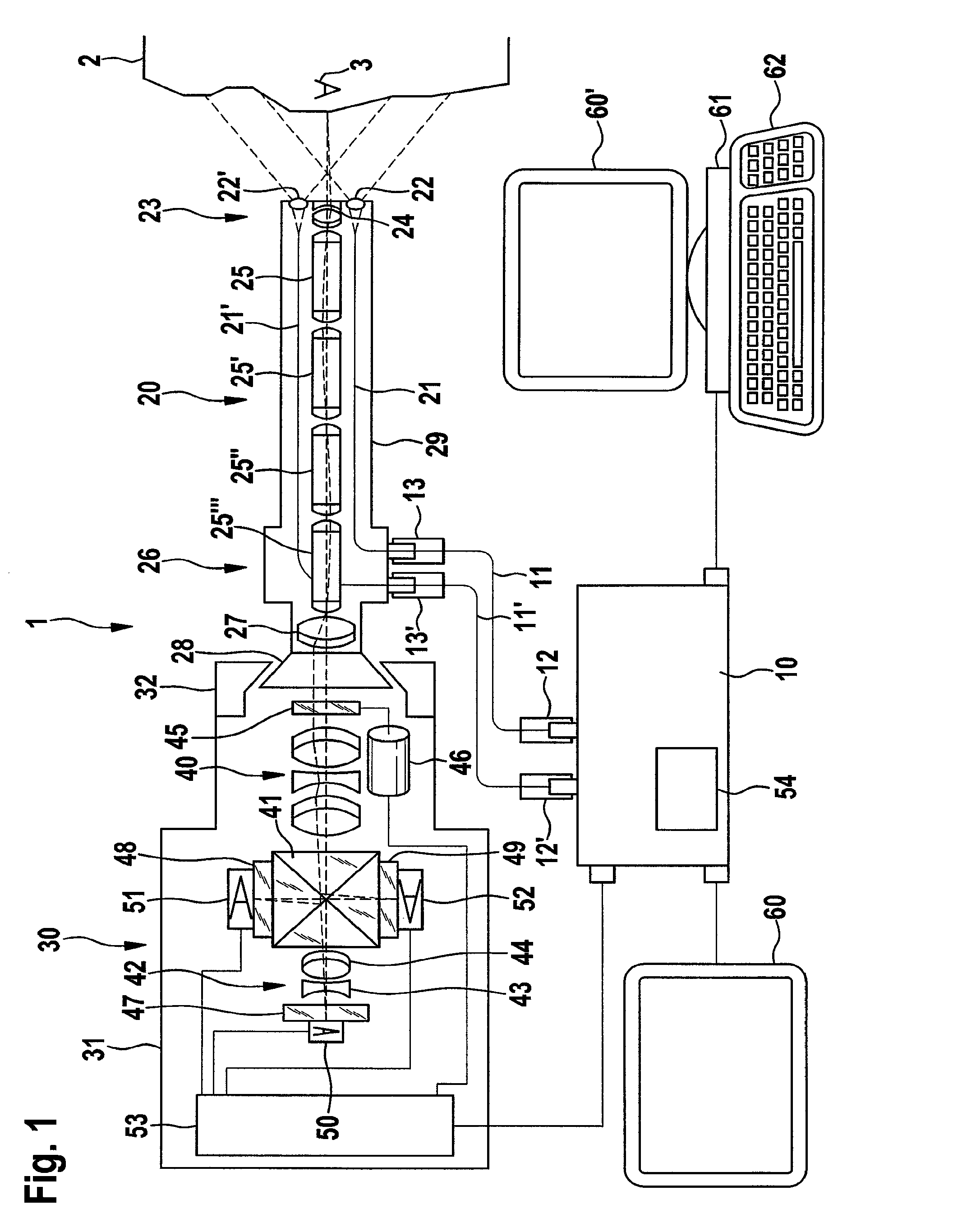
[0062]According to FIG. 1, an inventive apparatus 1 includes a light source 10. In the illustrated preferred embodiment, the light source is configured for generating a continuous, for instance sinus-shaped, modulated measuring beam and a white light illumination. For transmitting both types of beam onward, light conducting cables 11, 11′ are provided respectively, and said cables can be connected by connections 12, 12′ with the light source 10 and by connections 13, 13′ with the endoscope 20. In a corresponding coupling or by using a supercontinuum laser, both types of beam can also be transmitted by a single light conductor. The light source can also be integrated in the endoscope.

[0063]The measuring beam and the white light are conducted to the end 23 close to the object (the end remote from the observer, or distal end) of the endoscope 20 by the endoscope light conductors 21, 21′. The enlarging lenses 22, 22′ situated there serve to uniformly distribute the illuminating beam ont...


PUM


Abstract

An endoscopic apparatus includes a light-generating mechanism for generating at least one modulated measuring beam, a light-transmitting mechanism for conducting the measuring beam onto an area to be observed, where the light-transmitting mechanism includes an illuminating lens, in addition to a light-imaging mechanism for imaging a signal beam from the area to be observed at least onto a phase-sensitive image sensor, which includes a number of pixels, where the light-imaging mechanism includes an imaging lens. At least one additional image sensor is provided and the light-imaging mechanism includes a beam-splitter and / or an optical switch, where at least one adaptive lens is provided for adapting the fields of vision of the image sensors. As a result, an apparatus is created for endoscopic 3D data collection that is suitable for various types of image sensors.

Description

CROSS-REFERENCE TO RELATED APPLICATIONS[0001]The present application claims priority of European patent application No. 09 00 4958 filed on Apr. 3, 2009 and German patent application No. 10 2008 018 636.8-51 filed on Apr. 11, 2008.FIELD OF THE INVENTION[0002]The present invention relates to an apparatus for endoscopic 3D data collection as well as a related method.BACKGROUND OF THE INVENTION[0003]Apparatuses and methods for endoscopic 3D data collection are known in the art. For instance, U.S. 20060055942 A1 discloses a method for endoscopic distance measuring that is based on parallax shift of projected measuring points onto the observed object. Methods of this type are relatively robust, but the precision depends decisively on the triangulation base, which is always closely limited in endoscopic applications. In addition, these methods must make do with relatively few data points.[0004]Patent DE 10 2006 017 003 A1 discloses an endoscope for depth acquisition in which a modulated l...

Claims


Application Information

Patent Timeline
Patent Type & Authority Patents(United States)
IPC IPC(8): A61B1/04A61B5/103A61B5/00
CPCA61B1/00096A61B1/00193A61B1/0638A61B1/045A61B1/0684G02B23/2415G01S17/89G01S7/4812G01S7/4813G01S7/4818A61B5/1076A61B1/00009G01S17/894A61B1/00194A61B1/0655
Inventor KRATTIGER, BEAT
Owner STORZ ENDOSKOP PROD GMBH
Why Eureka
Try Eureka