Silver-containing foam structure

a foam structure and silver technology, applied in the field of wound dressings, can solve the problems of slow release of silver from the structure, insufficient in other applications, and inability to meet the needs of patients, and achieve the effect of reducing the amount of viable pseudomonas

Active Publication Date: 2012-09-11
MOLNLYCKE HEALTH CARE AB
View PDF26 Cites 11 Cited by
  • Summary
  • Abstract
  • Description
  • Claims
  • Application Information

AI Technical Summary

Benefits of technology

[0014]Preferably, the antibacterial characteristics of the foam structure is such that a circular sample of said foam having a diameter of 20 mm and a thickness of 5 mm, when exposed to 10 ml bacteria-containing simulated wound fluid (a 1:1 solution of fetal calf serum and peptone water (aqueous solution containing 0.9% (wt) NaCl and 0.5% (wt) peptone)) at a temperature of 35° C.+ / −2° C. according to reference method ASTM E 2149, is able to reduce the amount of viable Pseudomonas aeruginosa cells from 106 to less than 102 in 72 hours, and to reduce the amount of viable Staphylococcus aureus cells from 106 to less than 102 in 120 hours.
[0016]Accordingly, the present invention provides a method for manufacturing an antibacterial and hydrophilic foam structure showing improved release of antibacterial silver ions over time.
[0023]As already mentioned, the antibacterial and hydrophilic polyurethane foam structure of the present invention can on one side be coated with a silicone gel, by adding one or more gel-forming silicone components thereto and allow the added silicone to form a cross-linked gel by curing. The cross-linked silicone gel used as coating of the antibacterial, hydrophilic polyurethane foam of the present invention can conveniently be characterised in terms of its tensile strength, penetrability and peel strength. As the term is used herein, “tensile strength” means the maximum tensile load which can be applied (by means of a standard Instron tester) to a 5 cm wide, 3 mm thick strip of the cross-linked silicone gel in question.

Problems solved by technology

The release of silver from the structure is generally slow, which is advantageous in some applications but may not be sufficient in other applications.

Method used


Image

  • Silver-containing foam structure
  • Silver-containing foam structure
  • Silver-containing foam structure

Examples


example 1

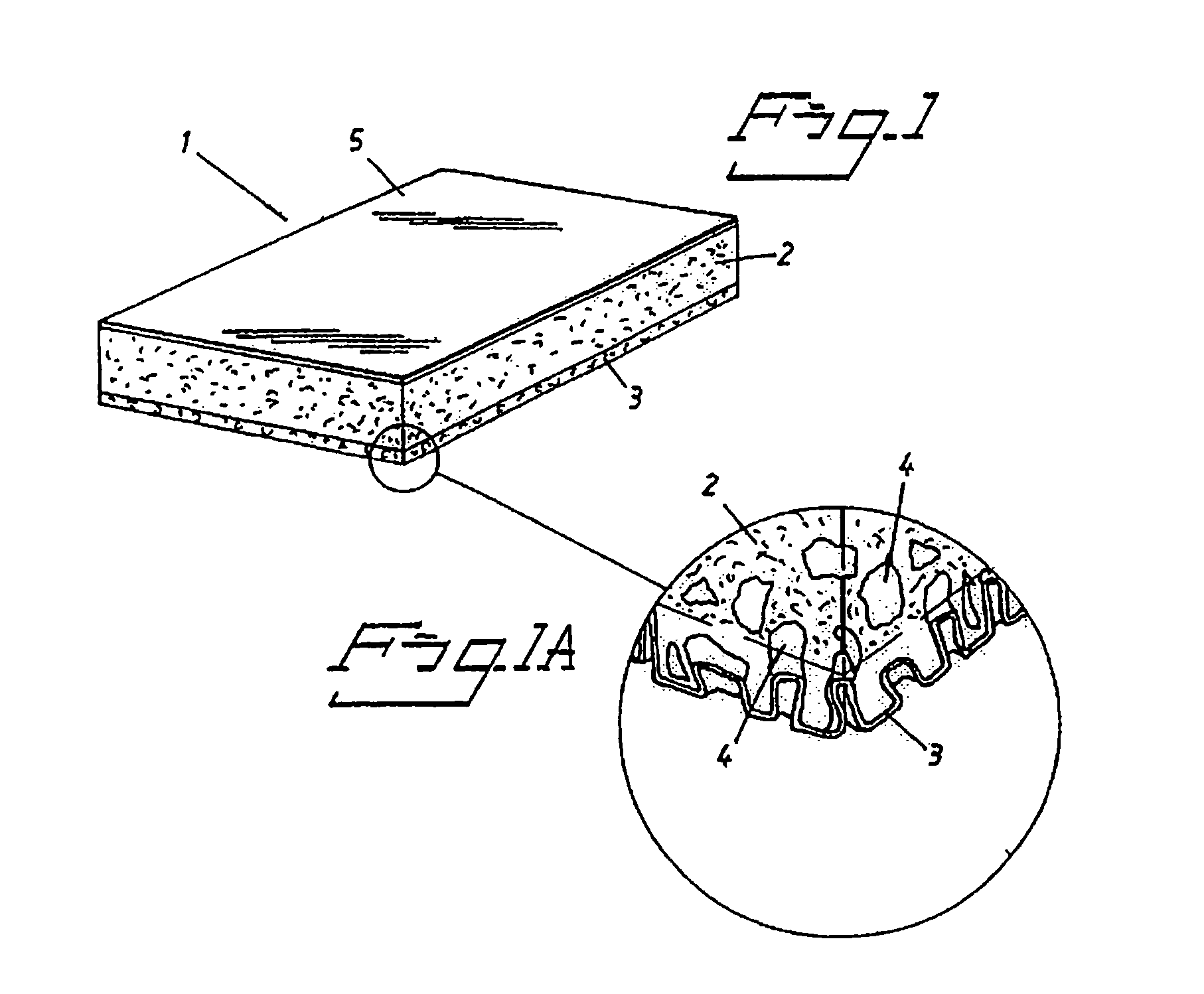
Preparation of the Foam Structure

[0059]A water phase for the foam-manufacturing process was prepared by dissolving / dispersing the non-ionic surfactant Pluronic F87, silver sulphate, and active carbon. The final concentrations of these constituents in the water phase amounted to 0.5% (wt) of Pluronic F87, and 2.2% (wt) of silver sulphate. The concentration of dissolved silver sulphate amounted to 0.8% (wt) and the rest of the silver sulphate was dispersed in the water phase.

[0060]Simultaneously, a mould lined with casting paper was prepared. The mould had a sufficient depth so that sheet-formed foam castings having a thickness of 5 mm could be produced.

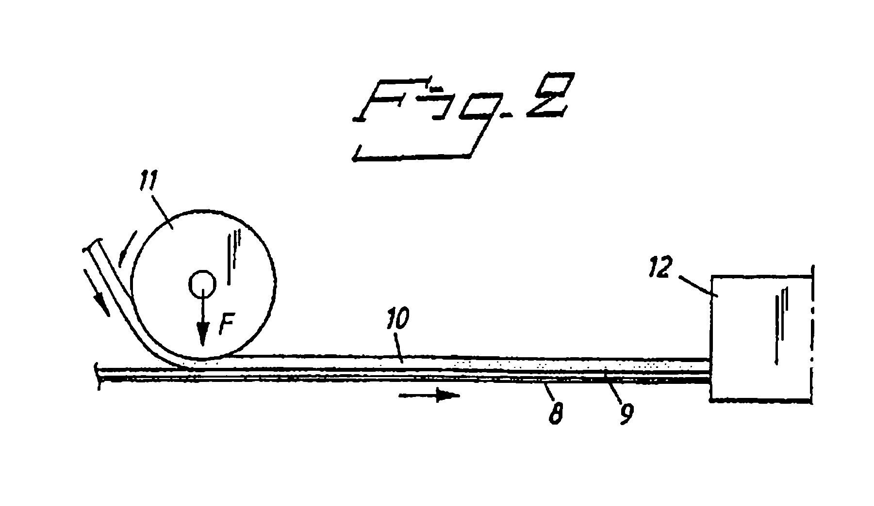
[0061]The pre-polymer Hypol 2001 (a isocyanate-terminated polyether) was added to the water phase in a dispensing and mixing equipment in an amount of 40% (wt) at room temperature. The resulting mixture was immediately transferred to the casting mould. The foaming amounted to 30 s, and then the foam was cured for 10 minutes. After curi...

example 2

Absorption of the Foam Material

[0062]Samples of the foam product produced in Example 1, Sample A, and two commercially available products, Sample B as described in WO2002062403 and Sample C as described in U.S. Pat. No. 5,681,575(A) and U.S. Pat. No. 5,837,275(A), were cut into 6×6 cm test pieces and weighed. Subsequently, the test pieces were soaked in an excess amount of tap water. After three hours, the pieces were re-weighed. The results obtained are shown in Table 1:

[0063]

TABLE 1AbsorptionAbsorptionDry weight (g)Wet weight (g)(g / 36 cm2)(g / cm2)Sample A2.8235.532.70.91Sample B3.5228.525.00.69Sample C3.3133.029.70.82

[0064]The results show that the product of Example 1 (Sample A) has an as good or slightly better absorption capacity as commercially available products.

example 3

Silver Release

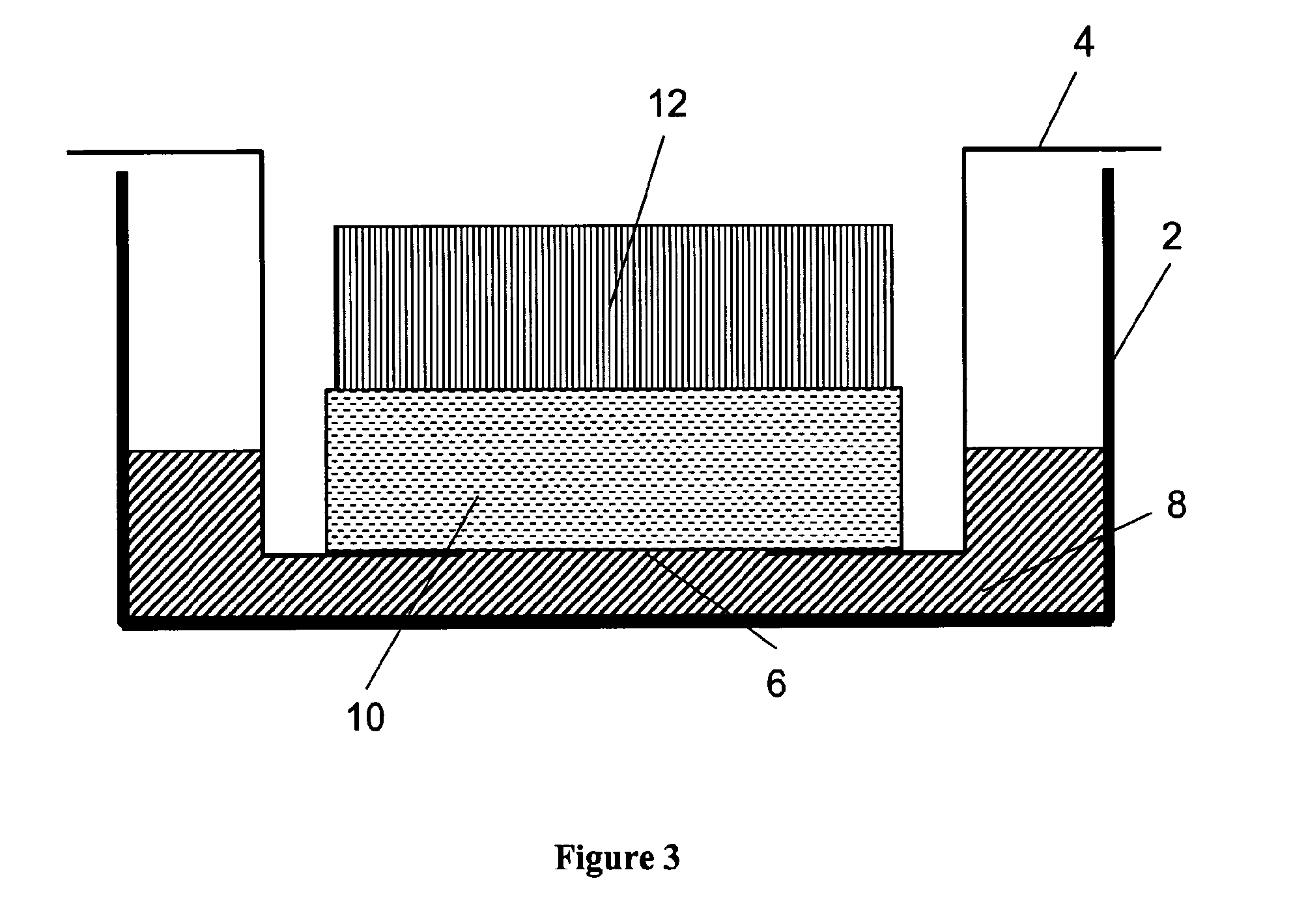
[0065]Circular samples having a diameter of 20 mm were punched out from the material produced according to Example 1, here referred to as Sample A, and two commercially available products, Sample B as described in WO2002062403 and Sample C as described in U.S. Pat. No. 5,681,575(A) and U.S. Pat. No. 5,837,275(A). FIG. 3 discloses some of the equipment for measuring silver release, namely a Falcon™ 6 well Multiwell unit (2) and a corresponding cell culture insert both from Becton Dickinson Labware (4) (The diffusion membrane in the bottom of the cell culture insert (4) was removed and replaced by a waterproof polyamide film. An opening (6) having a diameter of 12 mm was punched out from the bottom film. The dry sample (10) was placed in cell culture insert (4) on top of the opening (6). A weight (12) made of stainless steel, weighing 15 g and having a diameter of 20 mm was arranged on top of the sample (10) in order to compress and fix said sample to the bottom film.

[00...


PUM

PropertyMeasurementUnit
pore sizeaaaaaaaaaa
pore sizeaaaaaaaaaa
temperatureaaaaaaaaaa

Abstract

A method of producing a hydrophilic polyurethane foam structure containing a silver salt, chosen from the group of silver sulphate, silver citrate, silver acetate, silver carbonate, silver lactate and silver phosphate, or a mixture of these salts includes the steps of (a) providing a water phase containing a surfactant, and at least one silver salt, wherein the at least one silver salt is dispersed in the water phase; (b) providing a isocyanate-terminated polyether having functionality of more than (2); (c) mixing the water phase and the isocyanate-terminated polyether, immediately transferring the resulting mixture to a mould whereby a foam structure is obtained; and (d) drying the foam structure until it has a moisture content of at most 10% (wt). The hydrophilic polyurethane foam structure produced by the method and a wound dressing containing the foam structure are also described.

Description

[0001]The present invention relates to an antibacterial and hydrophilic polyurethane foam structure. More specifically, the antibacterial and hydrophilic foam structure contains an increased amount of silver both in the polymer matrix and inside the cells of the foam. Furthermore, the invention provides a method for manufacturing said antibacterial and hydrophilic foam structure.TECHNICAL BACKGROUND[0002]WO 97 / 42985 discloses a wound dressing comprising a layer of absorbent foam material which includes a pattern of holes. The holes open out on that side of the foam material which lies proximal to the wearer's skin when the dressing is worn, and the layer of foam material is coated with a layer of skin-adhering hydrophobic gel, wherein those end parts of the walls of the holes in the foam material that lie proximal to the wearer's skin when the dressing is worn are gel-coated. Nothing is disclosed about including particular antimicrobial or antibacterial compounds in the dressing.[00...

Claims


Application Information

Patent Timeline
Patent Type & Authority Patents(United States)
IPC IPC(8): A01N25/00C08G18/10C08G18/00A01N59/16A01N55/02A01N25/08A01N25/10
CPCA61L15/18A61L15/26A61L15/425A61L15/46C08J9/0066C08L75/04A61F2013/0091A61L2300/104C08J2375/04A61L2300/404A61L2300/602A61P31/04A61L15/22A61L15/42A61F13/02
Inventor ARESKOUG, STEFANJOHANNISON, ULFPRYDZ, MALIN
Owner MOLNLYCKE HEALTH CARE AB
Why Eureka
Try Eureka