Embossed plastic films for laminated glass

a technology of laminated glass and plastic films, which is applied in the direction of transportation and packaging, synthetic resin layered products, chemistry apparatuses and processes, etc., can solve the problems of trapped air, excessive deaeration of laminates, and air trapped, and achieve excellent deaeration behavior and good deaeration behavior

Active Publication Date: 2012-09-11
KURARAY EURO GMBH
View PDF7 Cites 0 Cited by
  • Summary
  • Abstract
  • Description
  • Claims
  • Application Information

AI Technical Summary

Benefits of technology

[0014]Films according to the invention have an especially good deaeration behavior during production of laminated glass since air can not only escape via valley bottoms between elevations but also perpendicular thereto via webs between elevations. This is an advantage in case of a premature edge sealing of the laminate since trapped air can still escape via other, open edge positions.
[0015]It is important that air trapped in the laminate can escape to numerous sides in a steady manner. By means of the surface structures according to the invention, sufficiently fast deaeration is possible and, simoultaneously, a melting of the eleveations that is too fast, such as with the island-shaped elevations on films according to U.S. Pat. No. 4,452,840 or EP 1 233 007, is avoided.
[0016]The webs on the film according to the invention provide the surface structure with a certain mechanical and thermal stability since under production conditions of laminated glass, initially the higher elevations melt off and the glass panels rest on the lower webs. Since air can still escape between the webs, an excellent deaeration behavior of the film in the lamination process results.

Problems solved by technology

Furthermore, barriers may be present in the channels, which prevent that deaeration of the laminate occurs too fast.
On the other hand, the trapped air should not escape too fast and hence uncontrolled since otherwise premature partial sealing of the laminate may occur.
In case of a melting of the elevations that is too fast, with such surface structures, there is the risk of partial sealing of the laminate.

Method used


Image

  • Embossed plastic films for laminated glass
  • Embossed plastic films for laminated glass
  • Embossed plastic films for laminated glass

Examples


Embodiment Construction

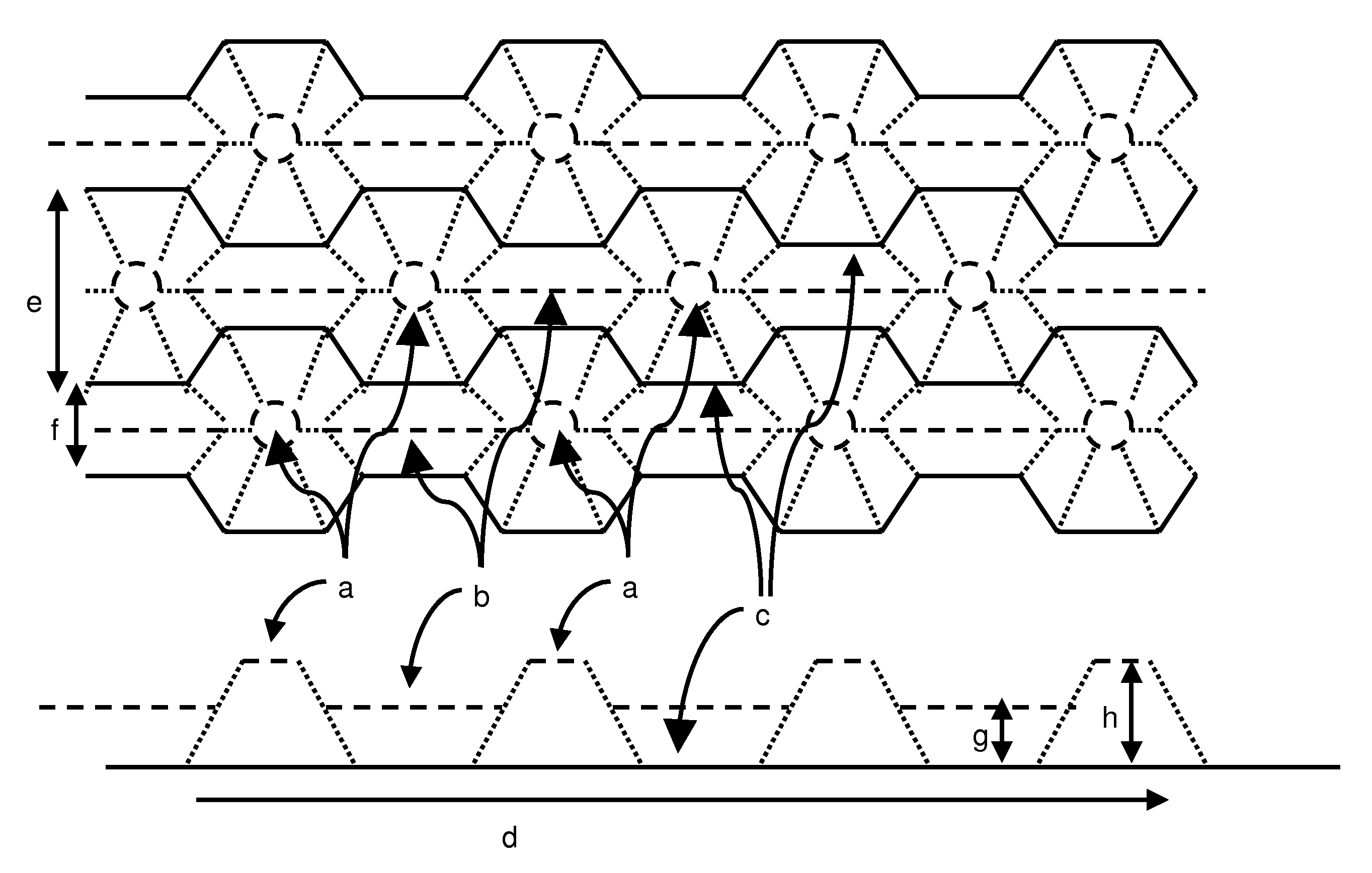
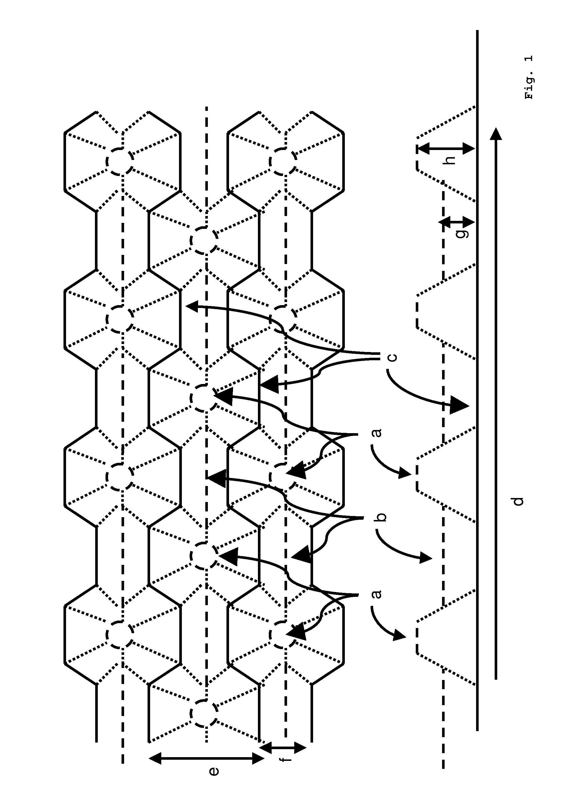
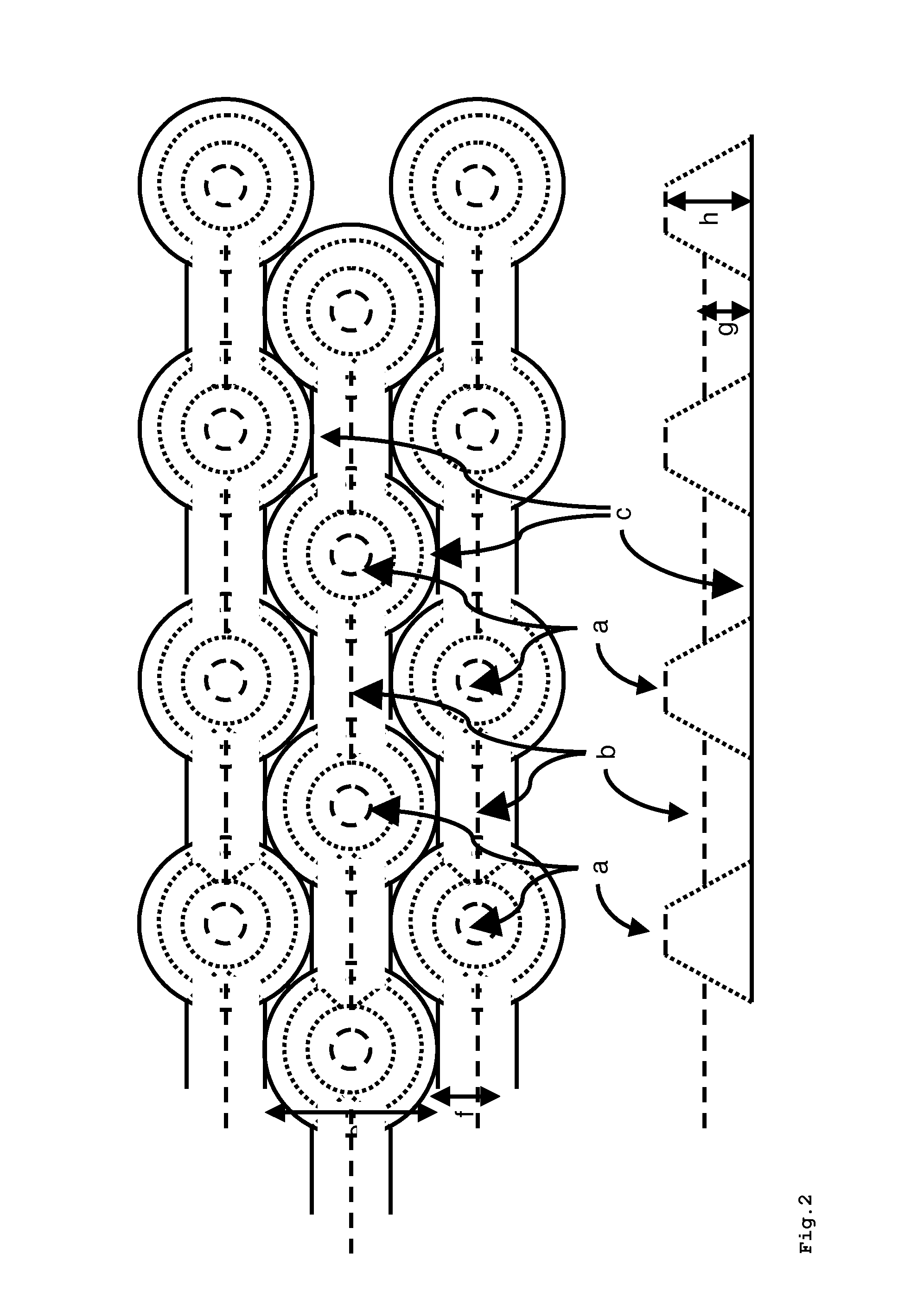
[0043]A plasticizer-containing PVB film made of 72.5% by weight of PVB, 25.0% by weight of 3G8 with potassium and magnesium salts as antiblocking agents and with a roughness Rz≦5 μm on both sides was embossed between a pressure roll made of rubber and an embossing roll having an inverse surface structure to FIG. 2. The film embossed on one side obtained in this manner was subsequently processed into a double-sidedly embossed film in a second embossing stage with identical properties on the second side.

[0044]

Pressure roll made of rubber:Hardness of rubber roll70 ± 5 Shore-ARubber roll diameter:255mmEmbossing roll (structure inverse of FIG. 2):Embossing roll diameter:245mmHeight of elevationsapprox. 135μmWidth of elevationsapprox. 310μmSpacing of elevations inapprox. 410μmrunning directionHeight of websapprox. 65μmWidth of websapprox. 130μm

[0045]FIG. 4 shows a surface picture of a film obtained in this manner.

[0046]The film was subsequently placed between two glass panels and processe...


PUM

PropertyMeasurementUnit
widthaaaaaaaaaa
heightaaaaaaaaaa
widthaaaaaaaaaa

Abstract

The invention relates to a plastic film, at least one side of which is provided with a surface structure comprising parallel rows of elevations (a). Said elevations (a) are interconnected by means of webs (b) that are at least 10 percent lower than the elevations (a). The inventive films can be used for producing laminated glass.

Description

[0001]The present invention relates to a plastic film suitable for the production of laminated glass, said plastic film having at least one side with a surface structure of elevations interconnected by webs, and the use of this plastic film.TECHNICAL FIELD[0002]The plastic films (interlayer films) employed in the production of laminated glass typically have a selectively applied roughness since that way, air trapped between the glass panels and the interlayer film can be removed in the lamination process.[0003]To adjust the roughness of the interlayer films, melt fracture extrusion methods or embossing methods are usually employed. The extrusion of plastic films under melt fracture conditions is disclosed for example in EP 0 185 863 B1 and provides films having an irregular surface.[0004]In the large-scale production of laminated glass panels, such as for example with motor vehicle windshields, films having an oriented, regular surface structure are preferably used. Such surface str...

Claims


Application Information

Patent Timeline
Patent Type & Authority Patents(United States)
IPC IPC(8): B32B3/00B32B3/30B32B17/10
CPCB32B3/30B32B17/10577B32B17/10761Y10T428/24942Y10T428/2457Y10T428/24479Y10T428/24612Y10T428/24669Y10T428/31518Y10T428/31601Y10T428/3163Y10T428/31616Y10T428/31649B32B27/22B32B27/304B32B27/306B32B2367/00B32B2375/00
Inventor STENZEL, HOLGER
Owner KURARAY EURO GMBH
Why Eureka
Try Eureka