Signal processing method and signal processing system

a signal processing and signal processing technology, applied in the field of signal processing methods and signal processing systems, can solve the problems of short processing time, inability to provide all images at high speed, and inability to produce thumbnail images, etc., to achieve the effect of reducing the amount of information, and reducing the amount of thinning processing

Inactive Publication Date: 2012-09-18
IMAGE PROCESSING TECH
View PDF20 Cites 3 Cited by
  • Summary
  • Abstract
  • Description
  • Claims
  • Application Information

AI Technical Summary

Benefits of technology

[0008]Accordingly, an object of the present invention is to provide a signal processing method and a signal processing system that can improve user-friendliness by raising the processing speed to be attained during imaging, and reducing a necessary volume of a recording medium through high-speed color separation processing and resolution conversion processing.
[0014]According to the present invention, a signal having a resolution little degraded can be provided. Further, since thinning processing is speeded up, an imaging apparatus can perform a high-speed continuous shooting action. Owing to a reduction in an amount of information, the number of images which the imaging apparatus can record in a recoding medium can be increased.

Problems solved by technology

Although a user requests an imaging apparatus to offer a sufficiently small output resolution, all the images cannot be provided at the high speed.
In addition, de-mosaicing processing and processing of producing compressed-signal information which are performed in the imaging apparatus require a processing time long enough to process all the images.
Further, there is a problem in that the processing of producing the thumbnail images may miss image information concerning a thin line or the like.

Method used


Image

  • Signal processing method and signal processing system
  • Signal processing method and signal processing system
  • Signal processing method and signal processing system

Examples


Embodiment Construction

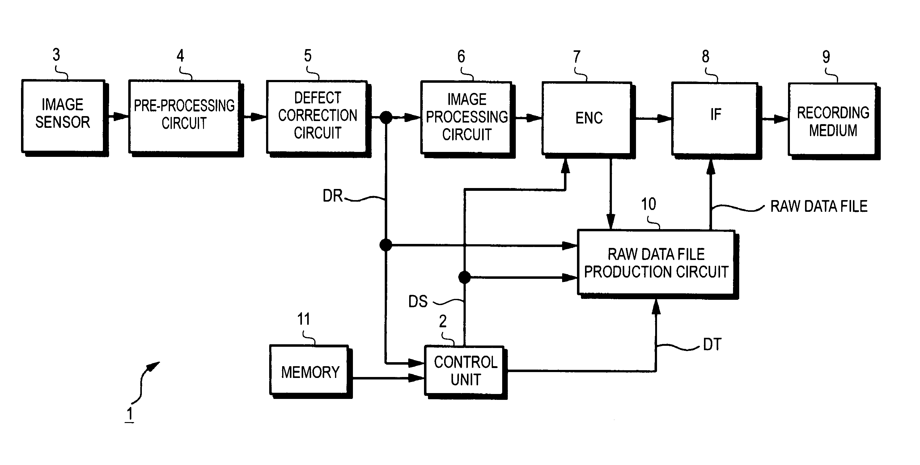
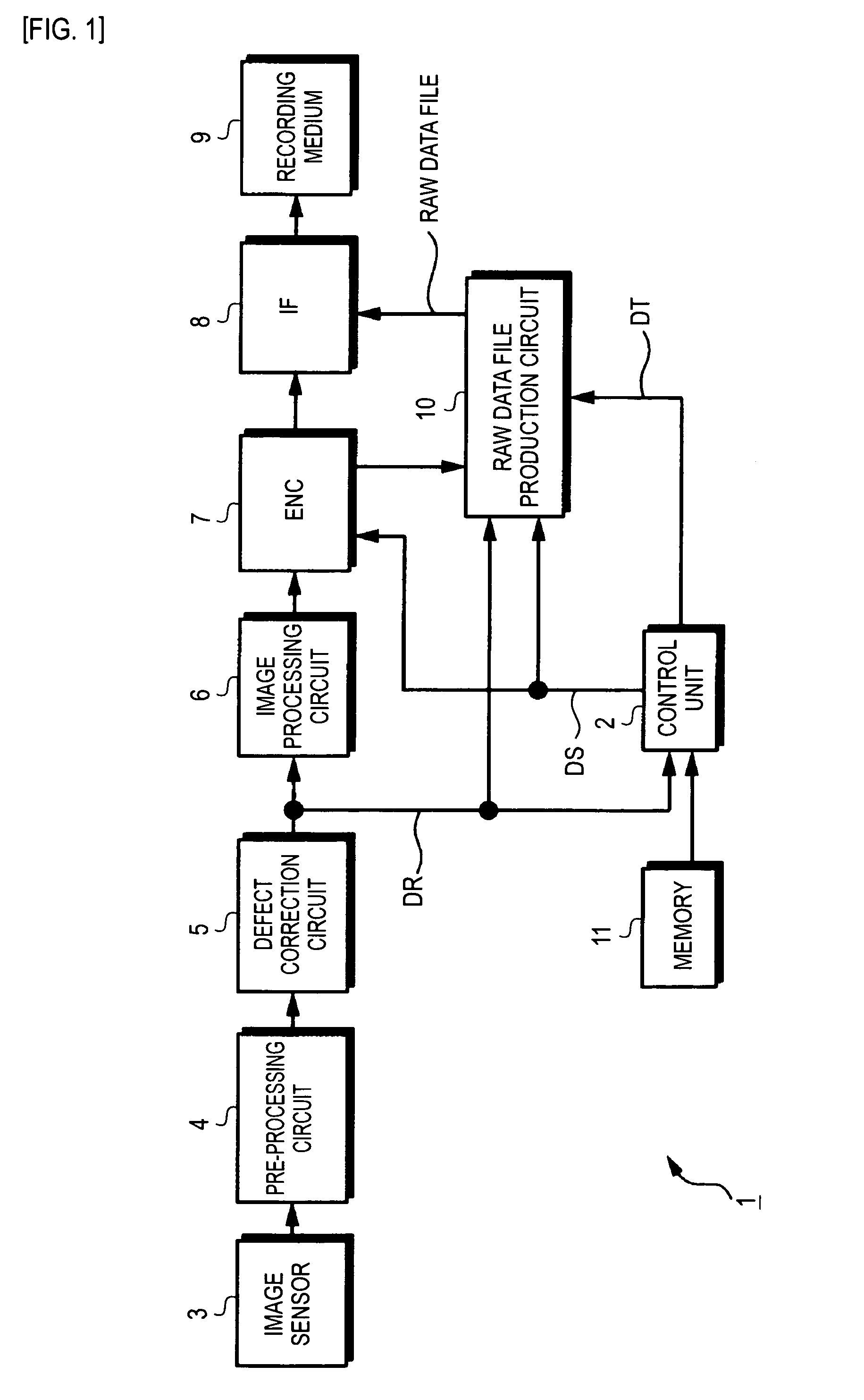
[0032]Referring to the drawings, an example of an imaging apparatus in accordance with an embodiment of the present invention, for example, a digital still camera 1 will be described below. The overall configuration of the embodiment is shown in FIG. 1. An imaging optical system (not shown) acts according to imaging conditions instructed by a control unit 2 formed with a microcomputer. Subject light having passed through the imaging optical system is routed to an image sensor 3.

[0033]The imaging optical system includes a zoom lens for use in enlarging or reducing a subject, a focus lens for use in adjusting a focal length, an iris (diaphragm) for use in adjusting an amount of light, a neutral density (ND) filter, and a drive circuit that drives the lenses and iris.

[0034]The image sensor 3 is a charge-coupled device (CCD), a complementary metal oxide semiconductor (CMOS), or the like. A pickup signal dependent on subject light is captured by the image sensor 3. The image sensor 3 may...


PUM


Abstract

A signal SG41 that has color signals thereof time-sequentially arranged in a color array corresponding to the color array in an image sensor 3 and that has not undergone resolution conversion is subjected to resolution conversion at a conversion rate (for example, ⅓) specified by a phase retention resolution conversion section 42. A de-mosaicing processing section 44 converts a signal SG42, which represents the order of the color array in the image sensor, into RGB signals SG44. A thin-line retention resolution conversion section 45 converts the signals SG44 into signals SG45 at a specified conversion rate (for example, ½). The signals SG45 are compressed by an encoder. In a recording medium 9, YC signals SG48 representing (640×480) pixels, the color signals SG42, a signal SG51 representing (640×480) pixels in the order of a color array and serving as thumbnail image data DT, and imaging information are recorded.

Description

CROSS-REFERENCES TO RELATED APPLICATIONS[0001]The present application is a national phase entry under 35 U.S.C. §371 of International Application No. PCT / JP2008 / 060718 filed Jun. 5, 2008, published on Dec. 11, 2008 as WO 2008 / 150017 A1, which claims priority from Japanese Patent Application No. JP 2007-151090 filed in the Japanese Patent Office on Jun. 7, 2007.TECHNICAL FIELD[0002]The present invention relates to a signal processing method and a signal processing system capable of being adapted to an imaging apparatus, for example, a digital still camera.BACKGROUND ART[0003]Image quality correction processing (may be called development processing) such as gamma processing, automatic white balance processing, hue correction processing dependent on an imaging mode, frequency characteristic correction processing, or noise reduction processing is performed on a pickup signal obtained from an image sensor such as a charge-coupled device (CCD), that is, image data obtained as a result of ...

Claims


Application Information

Patent Timeline
Patent Type & Authority Patents(United States)
IPC IPC(8): H04N5/228H04N5/76
CPCG06T3/4015H04N5/347H04N9/045H04N25/46H04N23/84H04N25/134H04N5/262G06T3/00H04N23/12
Inventor SAKAGAMI, JUNICHI
Owner IMAGE PROCESSING TECH
Why Eureka
Try Eureka