Mounting device

a technology of mounting device and sleeve, which is applied in the direction of curtain suspension device, sheet joining, building scaffold, etc., can solve the problems of not having the required durability, unable to employ manifold uses of plastic hook-and-loop closure, and relatively difficult and complex structure of the surface according to this method, so as to increase the elasticity of the composite, facilitate the production of connection, and increase the effect of elasticity

Active Publication Date: 2012-09-25
GOLLE MATTHIAS +5
View PDF25 Cites 9 Cited by
  • Summary
  • Abstract
  • Description
  • Claims
  • Application Information

AI Technical Summary

Benefits of technology

[0007]Due to the simple construction of the mounting device according to the present invention, it is relatively uncomplicated and rapid to produce by simple metal processing techniques, such as punching, cutting, and bending. Moreover, the capability of the mounting device of clawing into a workpiece or component is increased and therefore the retention force of the mounting device is improved overall by the implementation of the fastening projections, in contrast to the essentially rounded fastening projections of WO 2004 / 028731 A1. In addition, increased elasticity is obtained by the curvature of the fastening projections, which also results in a loadable connection and improved damping in the event of movement absorption.
[0035]The tab blanks incised in the base plate are expediently produced using a laser beam or by punching. By using a laser beam, it is possible to incise even relatively small tab blanks precisely into the metallic base plate and thus achieve the most uniform possible implementation of the tab blanks. Punching simplifies and accelerates the production procedure as a relatively simple metal processing technique, because multiple tab blanks may be punched out at the same time. Above all in the latter case, it is preferable from a manufacturing viewpoint if a free punch is produced around the tab blanks as they are incised. The width of the free punch is typically one to three times the thickness of the base plate, preferably up to 2.5 times. The free punches are generally to have a width of not more than 4 mm, preferably not more than 1.5 mm, and particularly approximately 0.3 to 1.0 mm. The free punches surrounding the fastening projections—except for the connection section—make bending the tab blanks out of the base plate easier, for example. For this purpose and for the following steps—i.e., steps a) and b)—a rolling continuous method or a method using progressive tools may be executed. In this way, it is possible to execute the various steps of the method in one work step and / or by one tool and thus further optimize the overall production method. Instead of working with narrow free punches, which are advantageous in principle for greater stability, in some applications, sections having larger areas may also be used.

Problems solved by technology

However, these plastic hook-and-loop closures are not employable for manifold uses, because they do not have the required durability and temperature stability and / or are not electrically conductive.
Therefore, the structuring of the surface according to this method is relatively difficult and complex.
Furthermore, it is also not possible with the aid of the method to implement the projections with predefined specific shapes, which would be desirable for adapting the adhesive properties of the structured surface of the workpiece to the material structure of the workpiece to be connected.

Method used


Image

  • Mounting device
  • Mounting device
  • Mounting device

Examples


Embodiment Construction

[0062]In the various embodiments of the present invention illustrated in the figures, identical components are provided with identical reference signs.

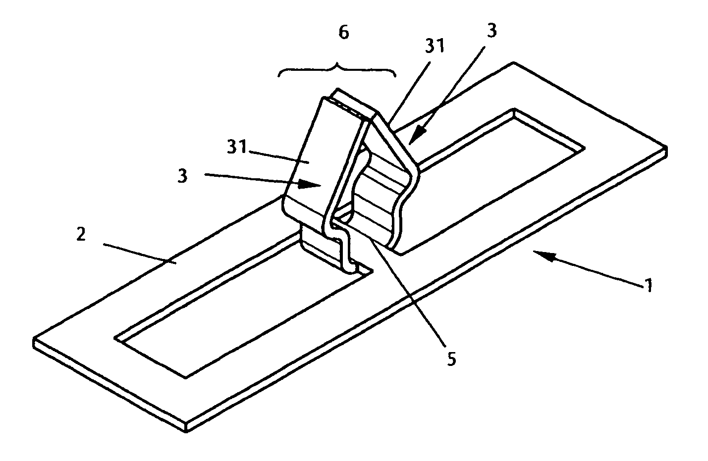
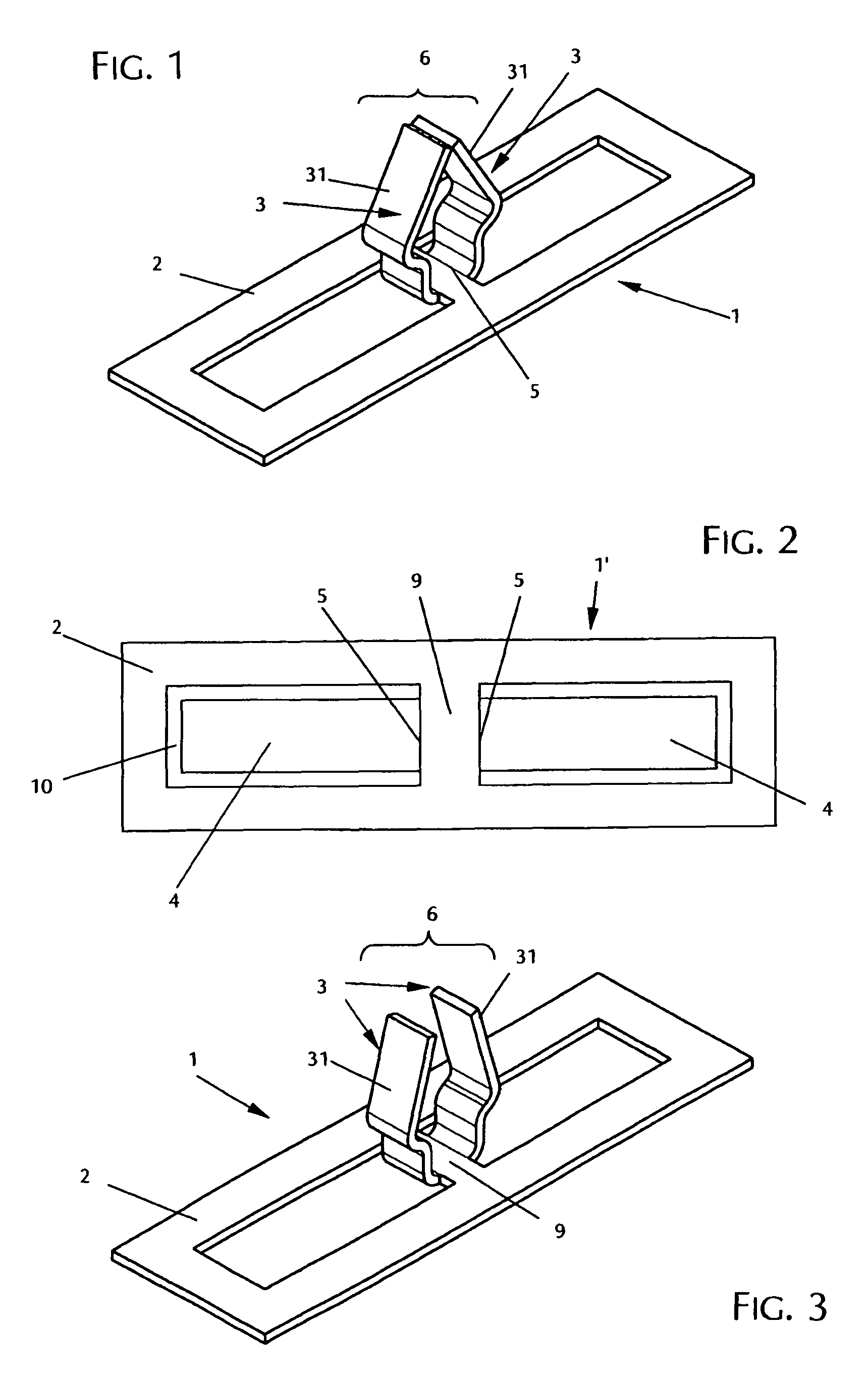
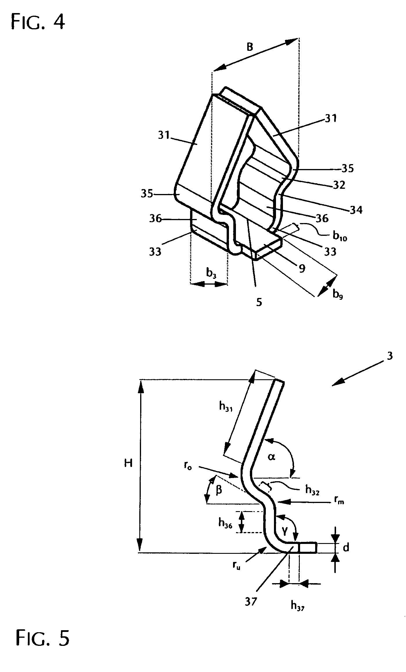
[0063]FIG. 1 shows a first exemplary embodiment of a mounting device 1 according to the present invention. It comprises a base plate 2, from which two fastening projections 3 are bent out projecting above one of the surfaces of the base plate 2. The production is performed from a blank 1′, as is shown as an example in FIG. 2. The blank 1′ is obtained by punching, or incising in another way, U-shaped free punches 10 in a metal plate made of spring steel, for example, in order to produce two rectangular, diametrically opposite tab blanks 4. These tab blanks 4 are still each connected to the base plate 2 at a connection section 5 and separated from one another by a web 9. After being cut free of the base plate 2, the tabs 4 are bent out of the plane of the base plate 2. The curves along the fastening projections 3 are expediently produce...


PUM

PropertyMeasurementUnit
total heightaaaaaaaaaa
angleaaaaaaaaaa
angleaaaaaaaaaa

Abstract

The present invention relates to a mounting device having a metallic base plate, from which multiple fastening projections project, as well as a method for producing this mounting device. The mounting device is obtainable by incising multiple tab blanks into the surface of the base plate while leaving at least one connection section per tab blank. The fastening projections are produced by bending the tab blanks out of the base plate, multiple fastening projections forming a group and the fastening projections within the group being bent in such a way that sections lying distal from the base plate are inclined toward the interior of the group and a section lying between the connection section and inwardly inclined section projects toward the exterior of the group.

Description

FIELD OF THE INVENTION[0001]The present invention relates to a mounting device having a metallic base plate, from which multiple fastening projections project, and a method for producing such a mounting device, and its use.BACKGROUND OF THE INVENTION[0002]In many industrial and other areas (e.g., construction, automobile construction, domestic, etc.), it is normally necessary to fix metallic components or workpieces or connect them with other components. It is frequently desirable for this purpose to produce the retainers and / or the connections in a simple and rapidly executable way, without special tools, such as welding or screwing tools, being required for fixing the fasteners. In the field of plastic components, such a retainer is achieved, for example, by using hook-and-loop closures as fasteners. However, these plastic hook-and-loop closures are not employable for manifold uses, because they do not have the required durability and temperature stability and / or are not electrica...

Claims


Application Information

Patent Timeline
Patent Type & Authority Patents(United States)
IPC IPC(8): A47G1/10
CPCF16B5/0642F16B5/0657F16B21/071F16B21/073
Inventor GOLLE, MATTHIASHEIN, CHRISTOPHHOEHE, KURTLASKE, MATTHIASRUESS, BERNDSO, HYUNWOO
Owner GOLLE MATTHIAS
Why Eureka
Try Eureka