

Floating card seal
a floating card and seal technology, applied in the field of rotating machines, can solve problems such as obstruction of fluid leakage, and achieve the effect of reducing wear
- Summary
- Abstract
- Description
- Claims
- Application Information
AI Technical Summary
Benefits of technology
Problems solved by technology
Method used
Image

Examples
first embodiment
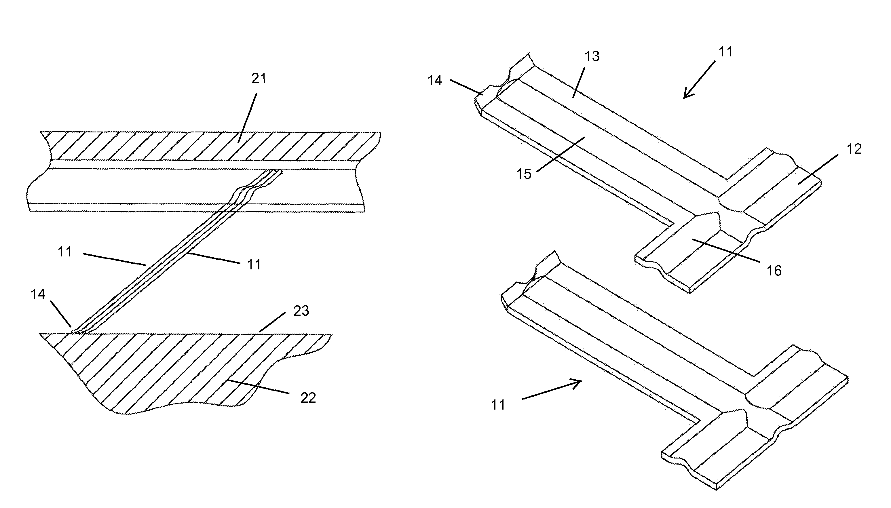
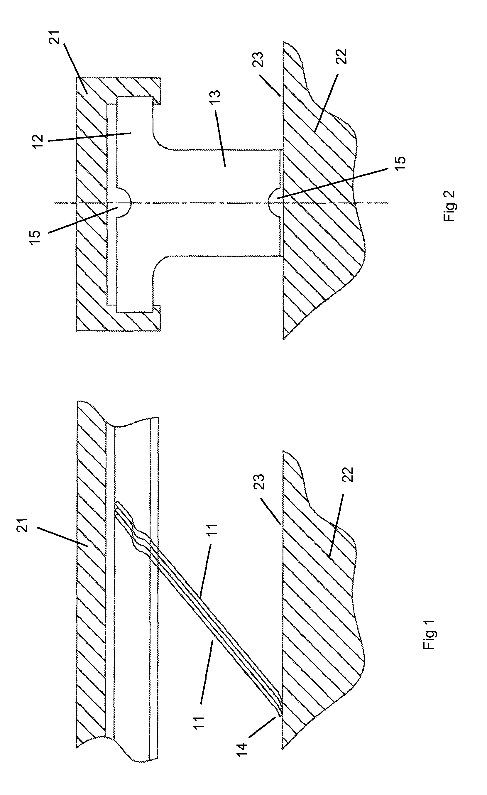
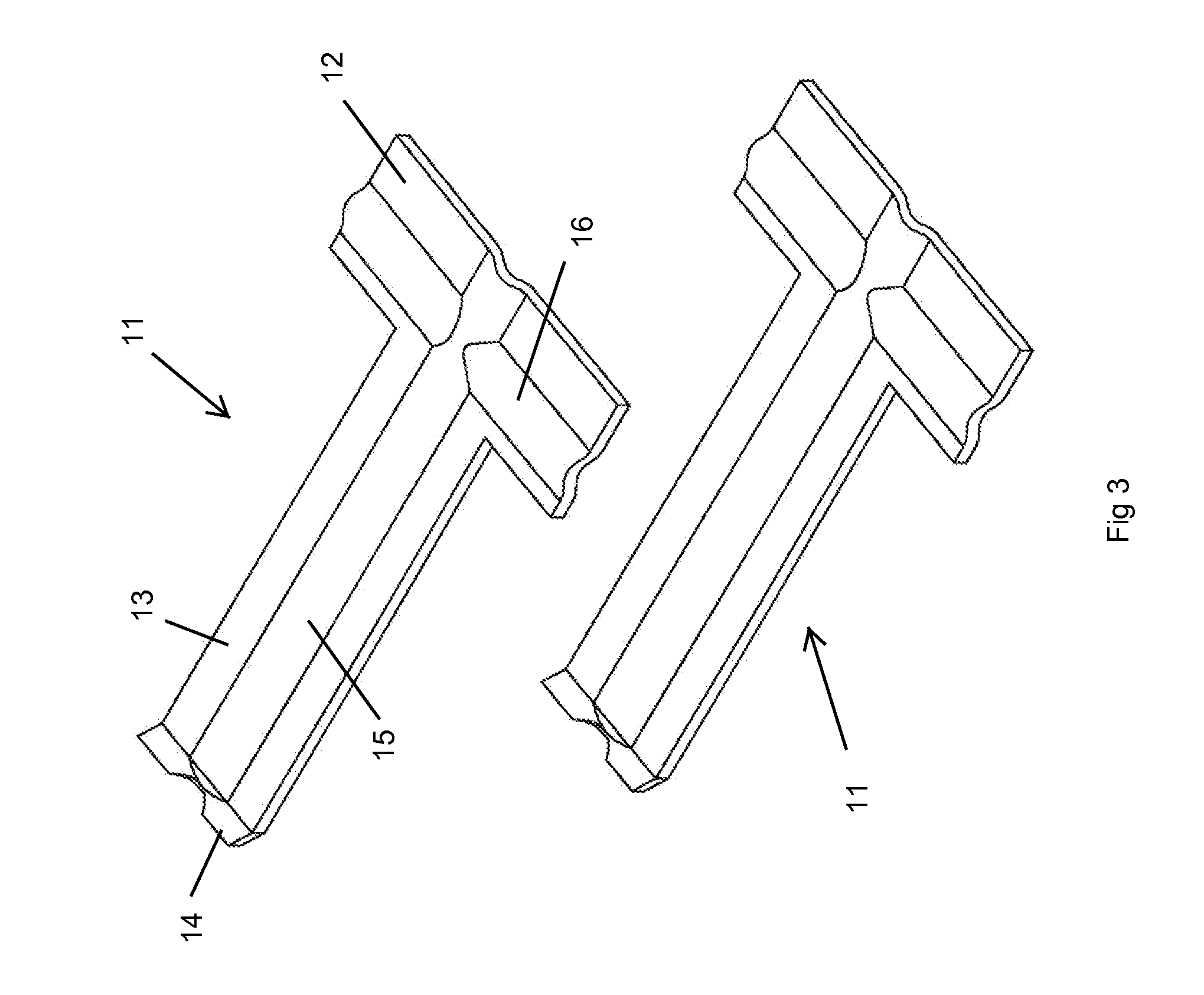
[0034]In the floating card seal shown in FIGS. 1 through 3, the individual leaf elements 11 that form the seal are the same leaf elements. Each leaf element can be formed by a punch and die stamp. FIG. 8 shows a side view of the leaf elements 11 of the floating card seal extending out from the stator 21 with the leaf elements 11 being angled at around 5 degrees from the rotational axis of the stator 21. In this embodiment, the leaf elements are around 0.7 inches in length with a spacing between adjacent tip ends 14 of around 0.06 inches. The leaf elements have a radius of around 28 inches measured from the tip ends 14. Adjacent leaf elements 11, when stacked on top of each other, form a gap of around 0.0014 inches based on a 28-inch seal radius with leaf elements 11 of around 0.005 inches in thickness. FIG. 9 shows this arrangement and FIG. 10 shows a stack of leaf elements 11 with a 5 degree slant from an axis of the stator 21.
[0035]FIGS. 10 and 11 show a second embodiment of the f...
second embodiment
[0036]FIG. 11 shows a cross section view of a stack of six of the leaf elements used in the floating card seal of the present invention. The first leaf elements 31 are alternating with the second leaf elements 32 so that the raised portion 34 forms a flow channel along a middle of the long axis of the leaf section and the two raised portions 33 form two flow channels on both sides of the flow channel formed by the single raised portion 34. These raised portions 33 and 34 also form abutment surfaces between adjacent leaf elements 31 and 32 to block parasitic leakage across the card seal.
[0037]The leaf elements 31 and 32 of the second embodiment are stacked alternating to form a complete annular arrangement of leaf elements around the stator so that the leaf section ends form an air riding surface over the smooth surface of the rotor as in the above first embodiment. The leaf section ends can also include the slanted end surfaces of the first embodiment. FIG. 12 shows the second leaf ...
PUM
 Abstract
Description
Claims
Application Information