Long range, low power, mesh networking without concurrent timing

a technology of mesh networking and long range, applied in the field of distributed networks, can solve the problems of limited application of state-of-the-art ugs systems, lack of commercially available low-power mesh networking solution for radios with multi-mile communications range, and may be under surveillance, so as to prolong the life of sensor nodes, reduce power consumption, and reduce deployment constraints

Inactive Publication Date: 2012-09-25
ADVANCED DISTRIBUTED SENSOR SYST
View PDF38 Cites 62 Cited by
  • Summary
  • Abstract
  • Description
  • Claims
  • Application Information

AI Technical Summary

Benefits of technology

[0018]Family relationships are used in this embodiment to effect routing. Generally, any messages to be directed to the base node are forwarded by a child node to its parent node. This routing mechanism requires only that a child node know its parent node and does not require the parent node to know its child nodes or the base node to know the message routing.
[0019]The present invention can provide a number of advantages depending on the particular configuration. By way of example, the wireless network can, through the use of mesh networking techniques, be self-forming and self-healing, allowing sensor nodes to be deployed in any fashion provided that the sensor nodes have a line-of-sight to at least one other sensor node (even if the sensor node has no line-of-sight to a base node). This capability can lessen deployment constraints and address several anticipated deployment scenarios. Cycling of the

Problems solved by technology

State-of-the-art UGS systems currently have limited applications for border monitoring as these existing systems do not offer wide area coverage.
Many of these areas of deployment are quite remote and therefore require relay stations to communicate with the command and control center.
As UGS are frequently deployed using intelligence gathered by field agents (suspected areas of operation), it is likely that the deployment area may be under surveillance by the adversary.
The largest single missing element in current UGS systems is the lack of a commercially available low-power mesh networking solution for radios with multi-mile co

Method used


Image

  • Long range, low power, mesh networking without concurrent timing
  • Long range, low power, mesh networking without concurrent timing
  • Long range, low power, mesh networking without concurrent timing

Examples


Embodiment Construction

The Network Architecture

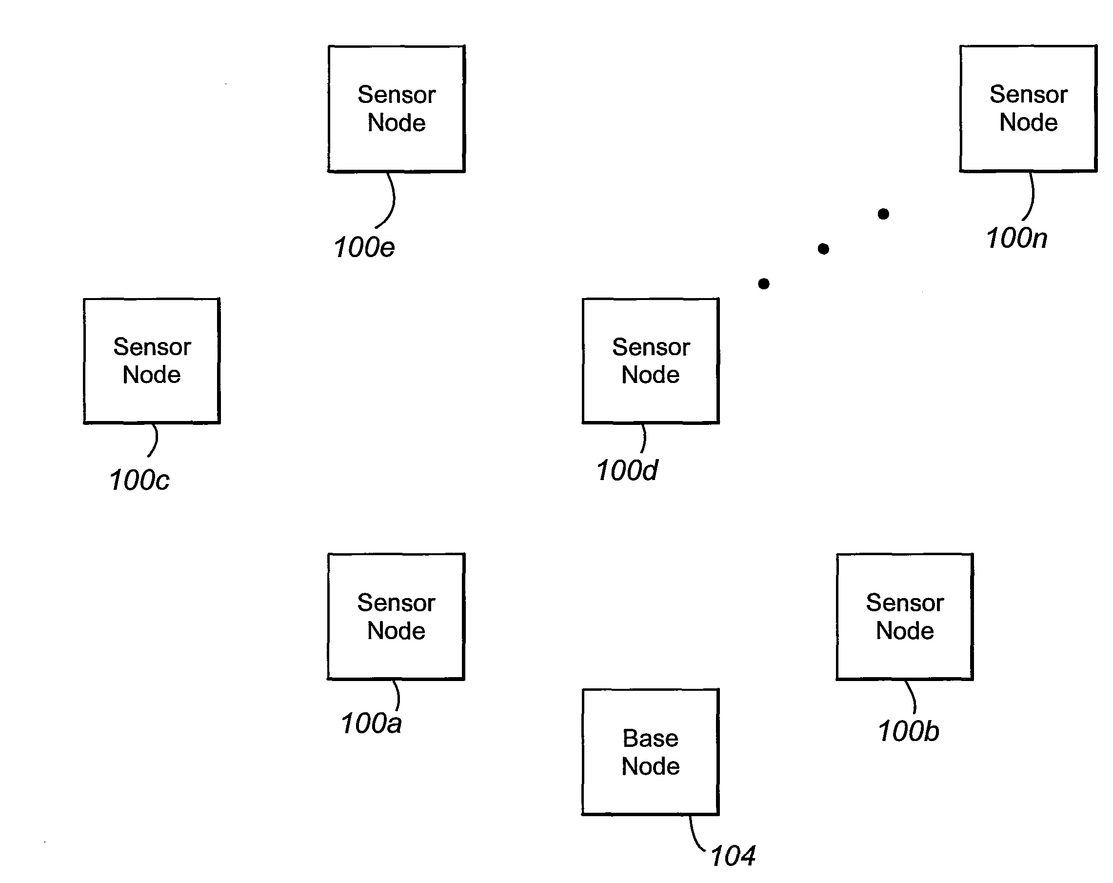
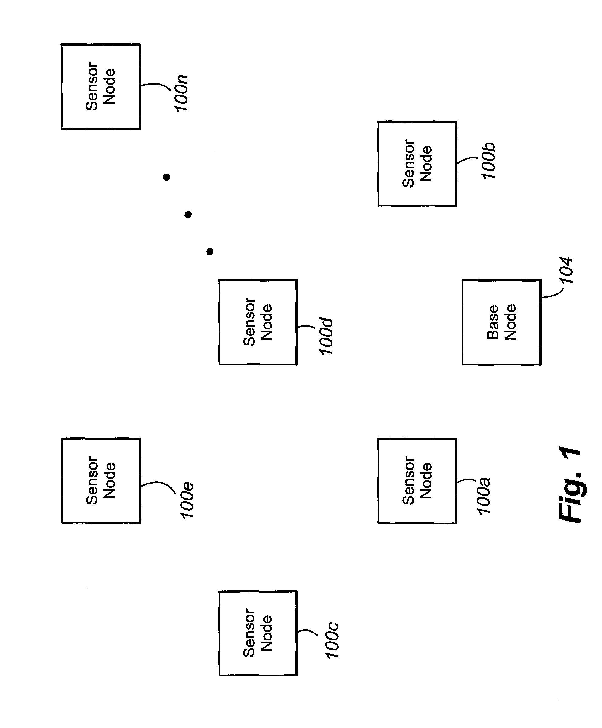
[0046]An embodiment of a network architecture according to a first embodiment will be discussed with reference to FIGS. 1-4. The network includes a number of spatially dislocated sensor nodes 100a-n in wireless communication with one another and with a base (gateway-equipped) node 104. The various sensor nodes 100a-n are grouped into families, each family including spatially proximal sets of nodes. For example, sensor node 100a is a parent to nodes 100c and 100d and a grandparent to node 100e. Node 100e is a child of node 100d, or, stated another way, node 100d is a parent of node 100e. As discussed below, the family groupings are used in routing messages through the network.

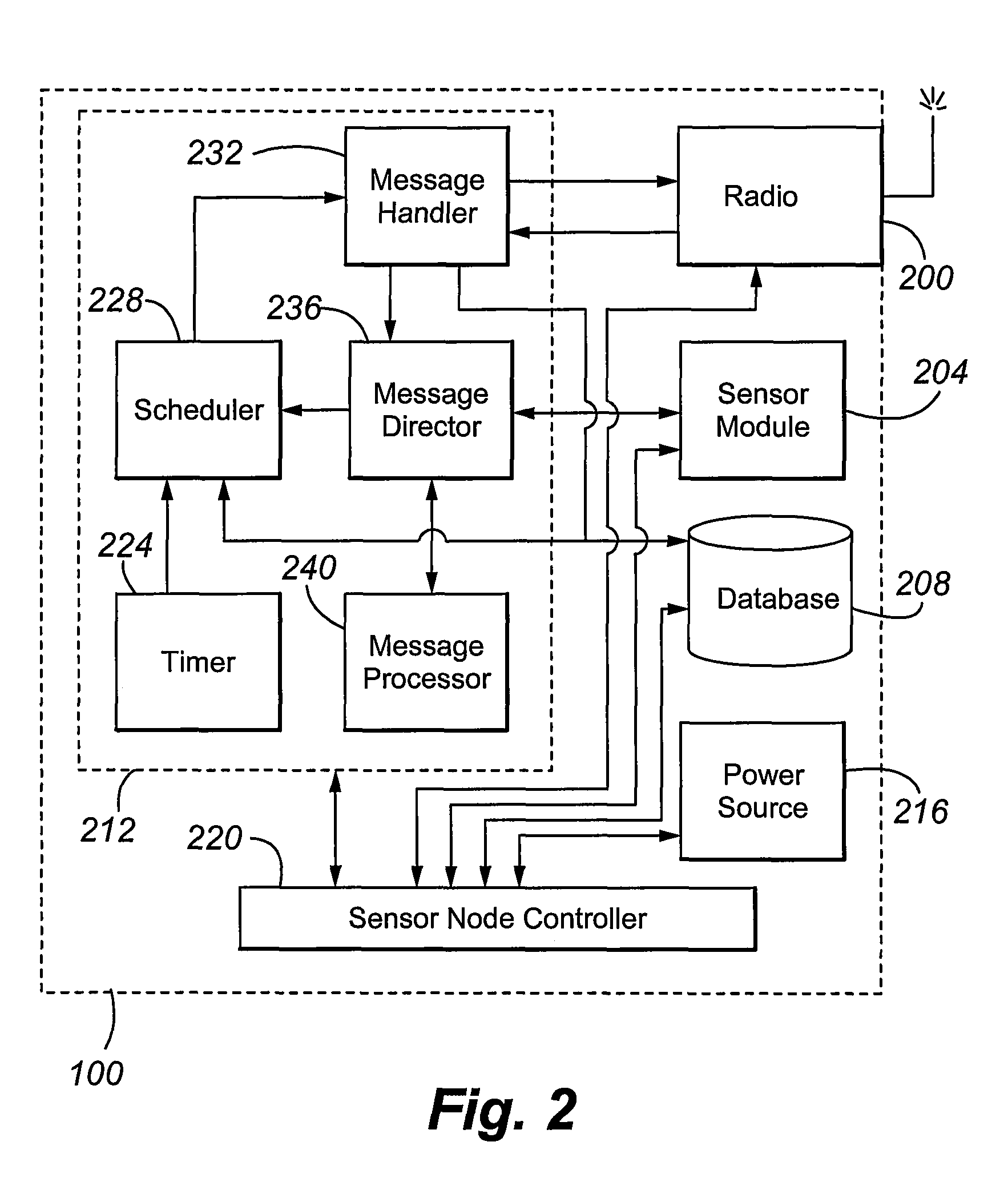
[0047]In one configuration, each node 100a-n includes a radio 200, a sensor module 204, a database 208, a mesh interface card 212, an internal power source 216, and a sensor node controller 220. The nodes can, of course, include more or fewer or different components depending on the appli...


PUM


Abstract

In one embodiment, a first sensor node 100 includes a radio to effect wireless communications; a sensor module 204 to sense a selected parameter; and a scheduler 228 that selects a listen time for the first sensor node, such that, during the listen time, the radio is activated and able to receive wireless signals and, during a time other than the listen time, the radio is deactivated and unable to receive wireless signals, and causes transmission to a second sensor node a first message. The first message includes a time offset from a transmission time of the first message, the time offset indicating a timing of a first listen time for the first sensor node. In response, the node 100 receives, from the second sensor node, a second message, with the time selected by the second sensor node to transmit the second message to the first sensor node being based on the time offset.

Description

CROSS REFERENCE TO RELATED APPLICATION[0001]The present application claims the benefits of U.S. Provisional Application Ser. No. 60 / 884,966, filed Jan. 15, 2007, of the same title, which is incorporated herein by this reference in its entirety.STATEMENT REGARDING FEDERALLY SPONSORED RESEARCH OR DEVELOPMENT[0002]The U.S. Government has a paid-up license in this invention and the right in limited circumstances to require the patent owner to license others on reasonable terms as provided for by the terms of Contract No. W9132V-06-C-0006 awarded by the United States Army.FIELD OF THE INVENTION[0003]The invention relates generally to distributed networks and particularly to distributed data collection networks.BACKGROUND OF THE INVENTION[0004]Distributed networked sensor systems are used in scientific, military, and law enforcement applications. By way of example, Unattended Ground Sensors (UGSs) have been considered as a low cost means to detect illegal border crossings along remote str...

Claims


Application Information

Patent Timeline
IPC IPC(8): H04B7/00
CPCH04W84/18H04W52/0206H04W74/0816Y02D30/70
Inventor MYERS, CHRISSTAARMANN, LEO JOHNJANSEN, DAVIDFRENCH, PATRICK
Owner ADVANCED DISTRIBUTED SENSOR SYST
Why Eureka
Try Eureka