Piston for a hydraulic motor having radial pistons, and a method of manufacturing such a piston

a technology of hydraulic motors and pistons, which is applied in the direction of pumps, mechanical equipment, engines with rotating cylinders, etc., can solve the problems of high seizure risk, considerable material waste, and the squeezing of the piston, so as to reduce friction, reduce the contact pressure, and improve the cooling effect of the piston

Inactive Publication Date: 2012-10-09
POCLAIN HYDRAULICS IND
View PDF11 Cites 0 Cited by
  • Summary
  • Abstract
  • Description
  • Claims
  • Application Information

AI Technical Summary

Benefits of technology

[0008]The recess has a concave surface that is substantially in the shape of a fraction of a cylinder, and that is of area larger than the area of the flat end wall of the piston, so that the area of heat exchange with the fluid present in the cylinder is increased, thereby facilitating cooling of the piston. Another reason why this cooling is more effective than the cooling in the prior art is that the fluid present in the recess is at a radial level that is offset outwards relative to the inner end, thereby making it possible to cool zones of the guiding and sealing surface that are somewhat remote from said inside end.
[0009]It should also be noted that the presence of the additional recess causes material to be removed from the base of the piston, thereby naturally enabling the piston to be lightened.
[0010]Compared with the blind holes of FR 2 648 512, the additional cradle-shaped recess, which is open at its ends situated in the guiding and sealing surface, enables the structure of the piston to be further lightened, enables the flexibility of the portions of the base of the piston that flank the additional recess to be further increased, and enables cooling to be enhanced, by increasing the area of contact between the cylinder and the fluid present in said cylinder under the base of the piston.
[0012]As indicated above, the pistons are subjected to tilt forces relative to their axes of translation, while the cylinder block and the cam are rotating relative to each other. The tilt forces are applied in planes perpendicular to the axis of relative rotation of the cylinder block and of the cam. The cradle-shaped recesses in the tops of the pistons extend parallel to that axis so as to enable the rollers present in said recesses to roll against the cam. In this situation, when the two recesses of a piston extend parallel to each other, the additional recess is also parallel to the axis of relative rotation of the cylinder block and of the cam. Because of the presence of the additional recess, the portions of the guiding and sealing surface that flank the recess present slight flexibility that enables them to deform in planes perpendicular to the axis of the recess. It is thus precisely in the planes in which the tilt forces are high that said portions of the guiding and sealing surface can deform slightly and can thus increase the mutually contacting surface areas. This makes it possible to limit the negative impact of the tilt forces while reducing the contact pressure and while avoiding excessive localized friction.
[0015]An object of the invention is to improve that state of the art by proposing a method that makes it possible to achieve higher manufacturing rates and that limits wastage of material.
[0019]In addition, each of the pistons obtained by means of this method has two recesses, thereby as indicated above, offering major advantages as regards limiting contact pressures, friction, and weight, and improving cooling of the pistons equipping a radial-piston hydraulic motor.BRIEF DESCRIPTION OF THE DRAWING FIGURES

Problems solved by technology

In addition, the friction between the guiding surfaces of the pistons and the inside surfaces of the cylinders causes local heating which, if it becomes excessive, can cause the piston to seize.
Unfortunately, in the portion of the guiding and sealing surface that is remote from said base, the cooling is not performed so well, and the risks of seizure can be high, in particular in the middle regions of the guiding and sealing surfaces.
That results in considerable wastage of material, it being possible for such wastage to be as high as about 50%.

Method used


Image

  • Piston for a hydraulic motor having radial pistons, and a method of manufacturing such a piston
  • Piston for a hydraulic motor having radial pistons, and a method of manufacturing such a piston
  • Piston for a hydraulic motor having radial pistons, and a method of manufacturing such a piston

Examples


Embodiment Construction

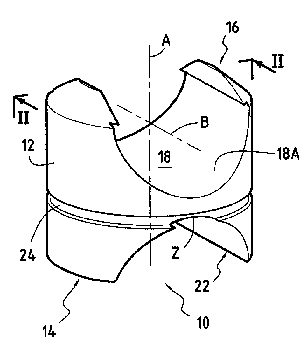
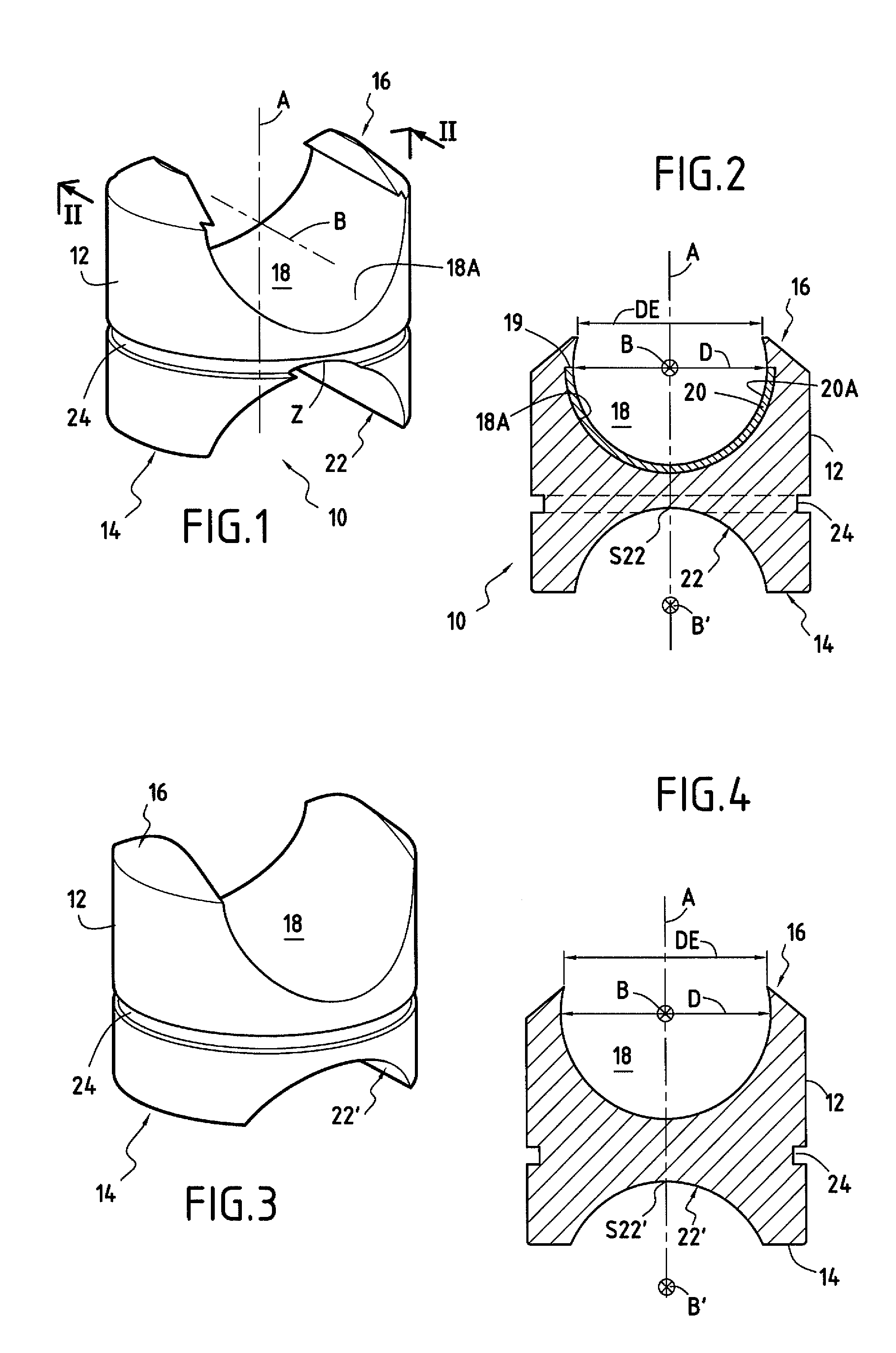
[0026]The piston of FIG. 1 comprises a body 10 having a guiding and sealing surface 12, a base 14 and a top 16.

[0027]The guiding and sealing surface is substantially in the shape of a cylinder having a base that is circular or of some other shape, the cylindrical shape of the surface matching the shape of the cylinder in which the piston is designed to slide. The base of the piston is its end that, when the piston is installed in the cylinder of a radial-piston motor, is closer to the end wall of the cylinder. The top of the piston is opposite from its base.

[0028]It can be seen that the top 16 of the piston is provided with a cradle-shaped recess 18. On the top of the piston, said recess forms a concave surface 18A that is substantially in the shape of a fraction of a cylinder of axis B perpendicular to the axis A of symmetry of the piston, which axis of symmetry is the axis along which the piston is designed to move in translation in the cylinder block of a motor having radial pist...


PUM

PropertyMeasurementUnit
shapeaaaaaaaaaa
symmetryaaaaaaaaaa
tilt forcesaaaaaaaaaa

Abstract

A piston for a hydraulic motor including a body having a guiding and sealing surface, a base, and a top, which top is providing with a cradle-shaped recess. The base is provided with an additional cradle-shaped recess whose concave surface faces in the direction in which the concave surface of the recess in the top faces.

Description

BACKGROUND OF THE INVENTION[0001]The present invention relates to a piston for a hydraulic motor having radial pistons, said piston comprising a body having a guiding and sealing surface, a base, and a top, which top is provided with a cradle-shaped recess.[0002]The cradle-shaped recess in the top of the piston serves to receive a roller or wheel designed to roll on the cam of the radial-piston hydraulic motor. In the meaning of the present invention, a cradle-shaped recess has a concave surface that is substantially in the shape of a fraction of a cylinder.[0003]While a radial-piston motor is operating, the cylinder block and the cam of said motor move in rotation relative to each other, and the pistons move radially in reciprocating motion inside the cylinders of the cylinder block, their above-mentioned rollers rolling on the cam.[0004]During this reciprocating motion, the guiding and sealing surface, which is the side surface of the piston (generally in the shape of a cylinder h...

Claims


Application Information

Patent Timeline
Patent Type & Authority Patents(United States)
IPC IPC(8): F04B1/04F04B1/107
CPCB23P15/10F03C1/0406F04B1/0408Y10T29/49249Y10T29/49798Y10T29/49252Y10T29/49789Y10T29/49796Y10T29/49794Y10T29/49792Y10T29/4979
Inventor LEMAIRE, GILLESNOEL, ALAIN
Owner POCLAIN HYDRAULICS IND
Why Eureka
Try Eureka