
Backlight module and light-emitting source package structure thereof

a backlight module and light-emitting source technology, applied in electrical devices, semiconductor devices, instruments, etc., can solve the problems of affecting the imaging quality of liquid crystal displays, the display cannot emit light by itself, and the temperature of the working environment is very high, so as to increase the heat dissipation efficiency, and improve the reliability of assembly

Active Publication Date: 2012-10-16
TCL CHINA STAR OPTOELECTRONICS TECH CO LTD
View PDF10 Cites 0 Cited by
  • Summary
  • Abstract
  • Description
  • Claims
  • Application Information

AI Technical Summary

Benefits of technology

This solution stabilizes the LED package structure, improves heat dissipation, and extends the lifespan of the LED chip by ensuring reliable thermal contact and efficient heat transfer, thereby maintaining the display's performance and preventing overheating.

Problems solved by technology

However, the liquid crystal material of the liquid crystal display cannot emit light by itself, and must depend upon an external light source.
But, the disadvantage of the LED package structure is that the temperature thereof during working is very high.
If the fixed plate of the backlight module could not timely dissipate heat generated by the LED package structure, not only the temperature of the surroundings of the LED package structure will obviously raise and result uneven temperature distribution in each of display blocks of the liquid crystal display, but also the high temperature of the display blocks of a liquid crystal display panel adjacent to the LED package structure may cause a reddish phenomenon due to the high temperature, resulting in affecting the imaging quality of the liquid crystal display.
Moreover, the raised temperature of the light-emitting-diode during working may easily affect the emitting efficiency and the working stability thereof, so that the lifetime thereof also may be lowered due to a long-term high temperature status.
Also, if the LED package structure are simply attached to the fixed plate only by an adhesive or fastened on the fixed plate by screws, the LED package structure and the fixed plate can not be directly in thermal contact with each other (or an insulation adhesive is sandwiched therebetween, or the interfaces therebetween are not in tight contact with each other), so that the heat-dissipation efficiency thereof will be affected in a certain degree.
Besides, after staying at a high temperature condition in a long time, the adhesives may be deteriorated and loss the viscosity, so that the LED package structure will be separated from the fixed plate.
If the heat of the LED package structure could not be timely taken off by the fixed plate, there will be a potential risk in overheat damage for the LED package structure.

Method used


Image

  • Backlight module and light-emitting source package structure thereof
  • Backlight module and light-emitting source package structure thereof
  • Backlight module and light-emitting source package structure thereof

Examples


Embodiment Construction

[0026]The foregoing objects, features and advantages adopted by the present invention can be best understood by referring to the following detailed description of the preferred embodiments and the accompanying drawings. Furthermore, the directional terms described in the present invention, such as upper, lower, front, rear, left, right, inner, outer, side and etc., are only directions referring to the accompanying drawings, so that the used directional terms are used to describe and understand the present invention, but the present invention is not limited thereto.

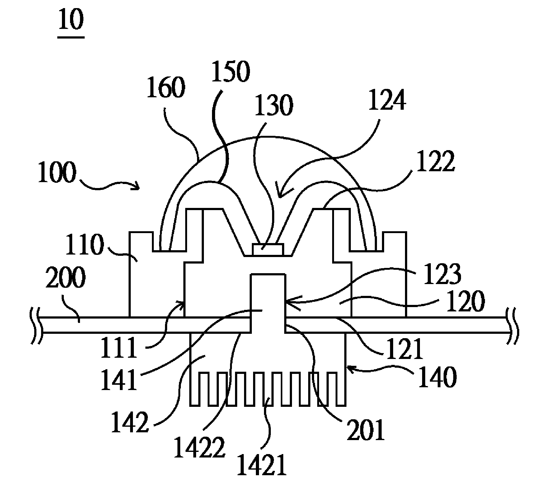
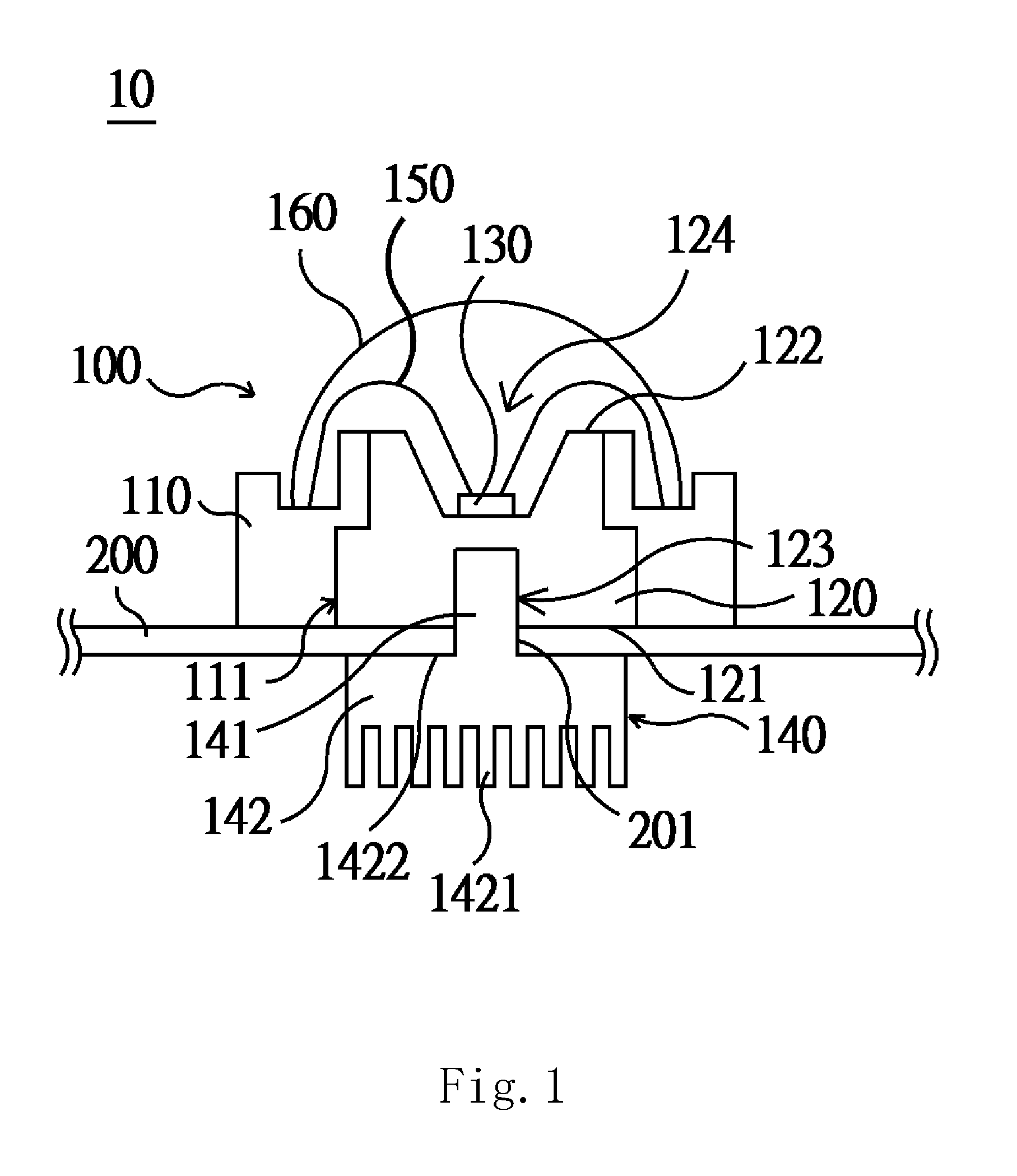
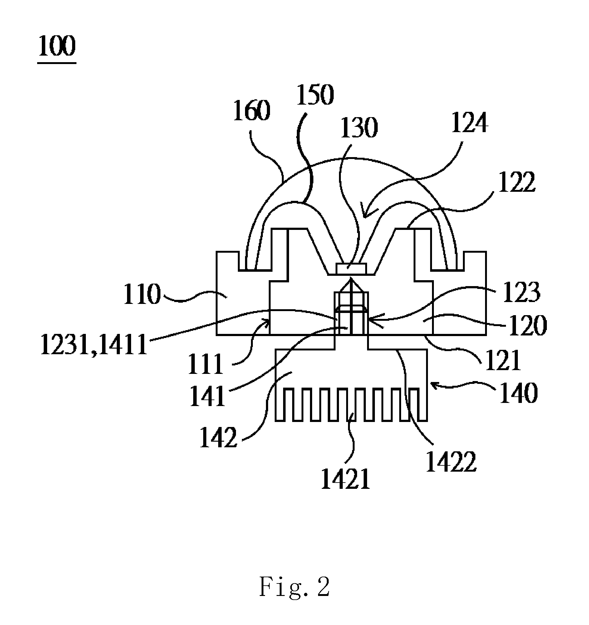
[0027]Referring now to FIG. 1, a schematic view of a light-emitting source package structure of a backlight module according to a first preferred embodiment of the present invention is illustrated, wherein a backlight module 10 is mainly applied to the field of liquid crystal display (LCD), and the backlight module 10 comprises at least one light-emitting source package structure 100 and a fixed plate 200, wherein each of ...


PUM


Abstract

The present invention provides a backlight module and a light-emitting source package structure thereof. The light-emitting source package structure comprises: a heat-dissipation base, at least one chip and a heat-dissipation fixing element. The heat-dissipation base has a connection hole. The heat-dissipation fixing element further has a connection post and a heat-dissipation fin with an abutting surface, and the connection post of the heat-dissipation fixing element passes through a through hole of a fixed plate to fix in the connection hole, so that for closely aligning the abutting surface of the heat-dissipation fin and can abut against the fixed plate. Thus, and the heat-dissipation base and the heat-dissipation fixing element are stably fixed on the both sides of the fixed plate to ensure the tightly abutting relationship with the fixed plate and enhance the assembly reliability. Meanwhile, the heat-dissipation fin can additionally increase the heat-dissipation efficiency of the heat-dissipation fixing element. Thus, the temperature of the chip can be surely lowered to prevent from lowing the working efficiency of the chip. Hence, it is advantageous for the chip to stably work, and the lifetime thereof can be increased.

Description

FIELD OF THE INVENTION[0001]The present invention relates to a backlight module and a light-emitting source package structure thereof, and more particularly to a light-emitting source package structure having a heat-dissipation fixing element to stably connect the light-emitting source package structure to a fixed plate and a heat-dissipation fin to dissipate heat and to a backlight module having the light-emitting source package structure.BACKGROUND OF THE INVENTION[0002]A liquid crystal display (LCD) is a kind of flat panel display (FPD), which shows images by the property of liquid crystal material. Compared with other display devices, the liquid crystal display has the advantages in lightweight, compactness, low driving voltage and low power consumption, and thus has already become the mainstream produce in the whole consumer market. However, the liquid crystal material of the liquid crystal display cannot emit light by itself, and must depend upon an external light source. Thus...

Claims


Application Information

Patent Timeline
Patent Type & Authority Patents(United States)
IPC IPC(8): H01L33/00
CPCG02F1/133603G02F2001/133628H01L33/642G02F1/133628H01L2224/48091H01L2924/00014
Inventor ZHOU, GEGE
Owner TCL CHINA STAR OPTOELECTRONICS TECH CO LTD
Learn More