Method for switching without any interruption between winding taps on a tap-changing transformer

a transformer and winding tap technology, applied in the direction of pulse generator, pulse technique, inductance, etc., can solve the problem that the known method is not suitable for use in a separate, universally usable on-load tap changer, and achieve the effect of high functionality

Active Publication Date: 2012-10-16
MASCHFAB REINHAUSEN GEBR SCHEUBECK GMBH & CO KG
View PDF7 Cites 3 Cited by
  • Summary
  • Abstract
  • Description
  • Claims
  • Application Information

AI Technical Summary

Benefits of technology

[0005]It is the object of the invention to provide a method of the kind described above that is of simple construction and has a high level of functionality and in which it is not necessary to be obliged to switch only precisely at the zero transition of the load current. A further object of the invention is to provide a corresponding method functionally capable in every case, i.e. without matching to the actual tapped transformer to be connected.SUMMARY OF THE INVENTION
[0017] necessarily arising in the commutation process at the side switching off is accepted predominantly by the varistor and only to a small extent by the IGBT switching off, particularly in the case of high commutation demands (high instantaneous value of the load current, high instantaneous value of an oppositely directed tap voltage, large leakage inductance of the switched tap).
[0018]This fact allows very simple and economic dimensioning of the electronic power switching groups, because the energy-receiving volume in the case of the varistor is flexibly variable and unequal to and larger than the very much smaller, more expensive volume, which is capable of volume variation only with difficulty, of the IGBT chip.
[0027]The smallest losses and shortest commutation times are achieved with simultaneous switching-off and switching-on of the two IGBT groups.
[0028]If in the course of the operating year an overlapping or gapped switching-over behavior in an order of magnitude of approximately ±10 microseconds should arise due to component ageing and shift in operating point in the electronic drive system, there is no resulting risk to function in the switching concept according to the invention. The sole consequences are moderately increasing commutation losses and a somewhat lengthened commutation time.
[0030]In the case of very high load currents it is possible to provide, in a manner known per se, a current zero transition detection and to perform the changeover or commutation process at very small instantaneous values of the load current with proximity in terms of time to the current zero transition. This measure leads to a drastic reduction in the current loading of IGBTs and varistors as well as in the commutation loss energy and to a shortening of the commutation time. Switching-over in the vicinity of the current zero transition allows a significant increase in the contact rating data of the on-load tap changer with unchanged hardware of the electronic power components.

Problems solved by technology

This known method is therefore not suitable for use in a separate, universally usable on-load tap changer not tailor-made for a specific transformer.

Method used


Image

  • Method for switching without any interruption between winding taps on a tap-changing transformer
  • Method for switching without any interruption between winding taps on a tap-changing transformer
  • Method for switching without any interruption between winding taps on a tap-changing transformer

Examples


Embodiment Construction

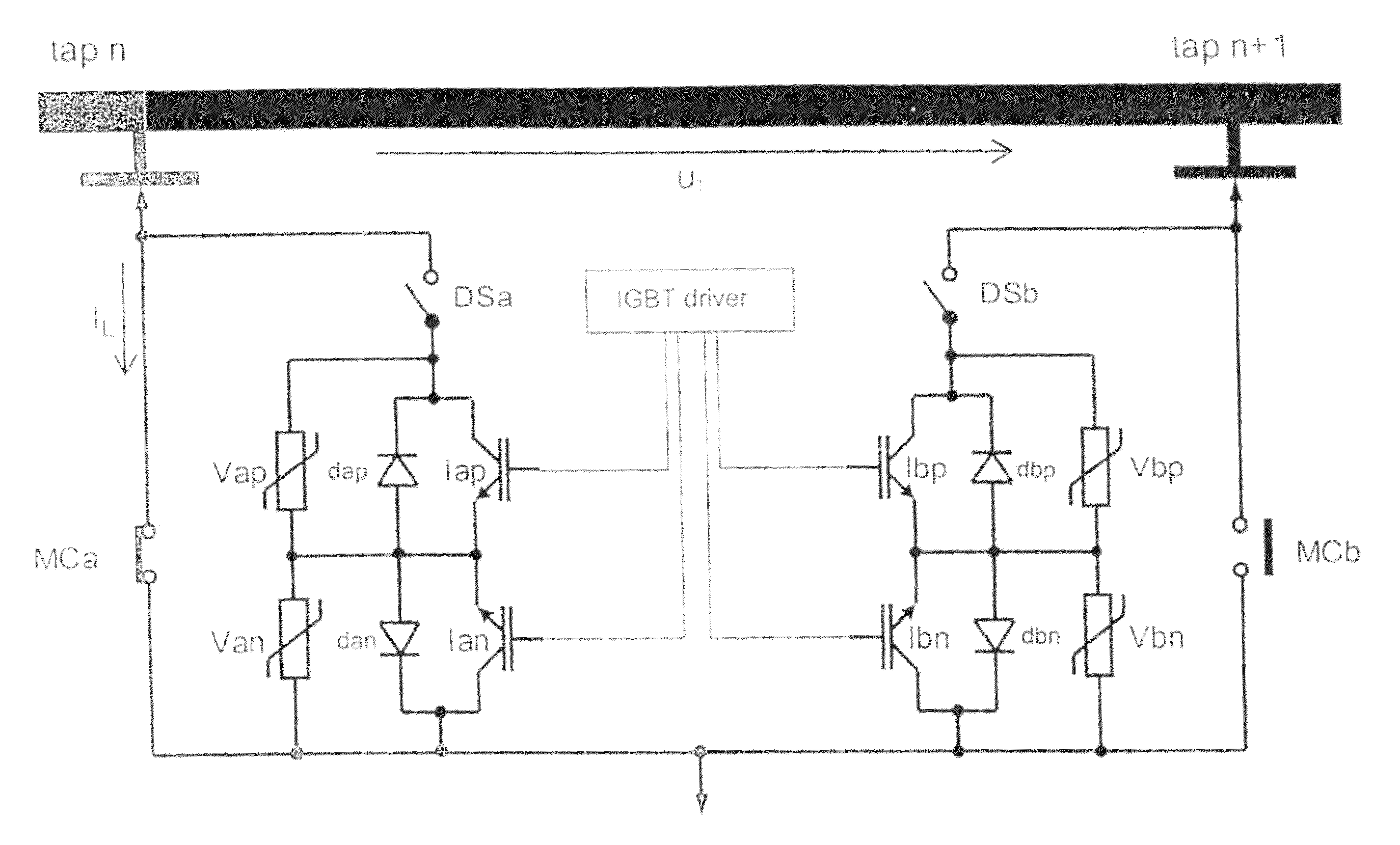
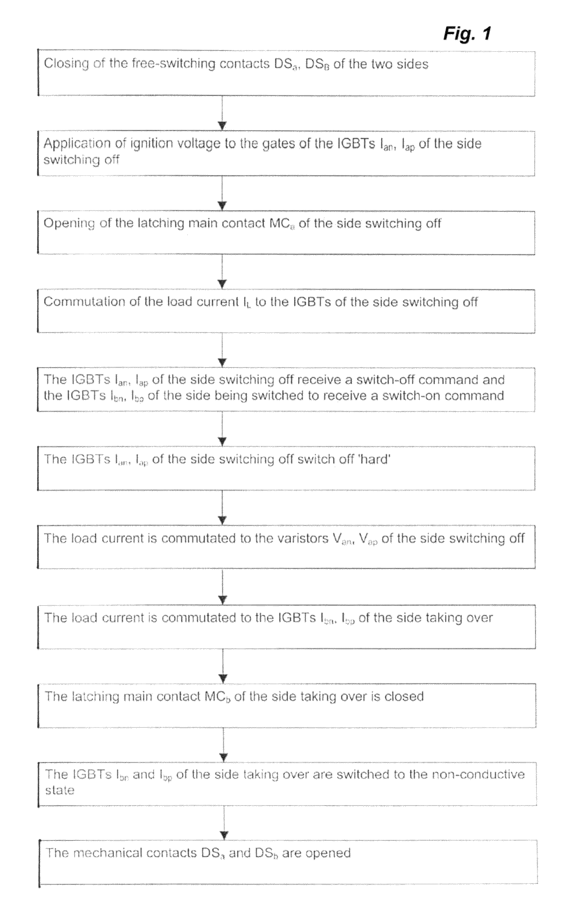
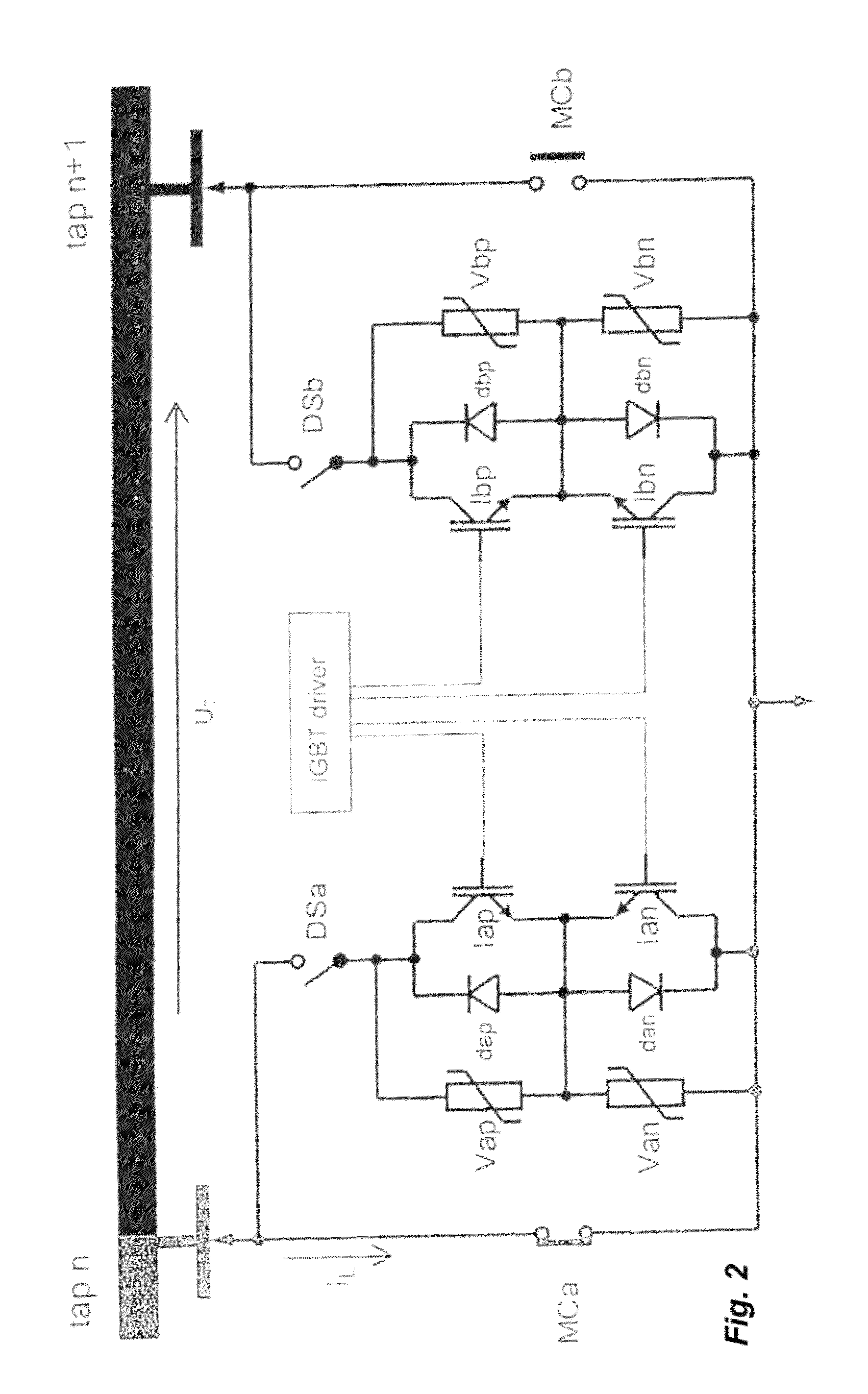
[0036]FIG. 1 shows a schematic flow chart of a first method according to the invention. The method proceeds from the fact that in the case of an on-load tap changer in which switching over from a previous winding tap of a tapped transformer to a new winding tap is to take place two load branches are provided which can be electrically connected with a common load output line by way of a mechanical switch DSa, DSb and a series circuit, which is arranged in series therewith, consisting of two oppositely connected IGBTs Ian, Iap; Ibn, Ibp each with a respective diode dn, dap; dbn, dbp in parallel, and that a respective varistor Van, Vap; Vbp is connected in parallel with each of the IGBTs. Each of the two load branches shall be capable of being bridged over by a latching main contact MCa or MCn.

[0037]As a first step the mechanical switches DSa and DSb, which act as free-switching contacts, of both sides are closed. Subsequently, an ignition voltage is applied to the gates of the IGBTs I...


PUM


Abstract

The invention relates to a method for switching without any interruption between two winding taps (tap n, tap n+1) of a tap-changing transformer, wherein each of the two winding taps is connected to the common load output line via in each case one mechanical switch (Ds) and a series circuit, arranged in series thereto, comprising two IGBTs (Ip, In) which are switched in opposite directions.

Description

CROSS REFERENCE TO RELATED APPLICATIONS[0001]This application is the US national stage of PCT application PCT / EP2008 / 007003, filed 27 Aug. 2008, published 4 Mar. 2010 as 2010 / 022751, and claiming the priority of PCT patent application PCT / EP2008 / 007003 itself filed 27 Aug. 2008, whose entire disclosures are herewith incorporated by reference.FIELD OF THE INVENTION[0002]The invention relates to a method of uninterrupted changeover by semiconductor switching elements between winding taps of a tapped transformer.BACKGROUND OF THE INVENTION[0003]Such a method with use of semiconductor switching elements is known from WO 2001 / 022447. The method described there operates not only with electrical switching means, i.e. insulated gate bipolar transistors known as IGBTs, but also mechanical contacts. It is designed so that the actual load changeover takes place at the zero transition of the load current by two IGBTs with diodes in rectifier-circuit arrangement. A necessary component of this kn...

Claims


Application Information

Patent Timeline
Patent Type & Authority Patents(United States)
IPC IPC(8): H03K17/60
CPCH01F29/04
Inventor BRUECKL, OLIVERDOHNAL, DIETERLESSMANN-MIESKE, HANS-HENNING
Owner MASCHFAB REINHAUSEN GEBR SCHEUBECK GMBH & CO KG
Why Eureka
Try Eureka