Bridgeless boost PFC circuits and systems with reduced common mode EMI

a technology of power factor correction and boost circuit, which is applied in power conversion systems, energy industry, sustainable manufacturing/processing, etc., can solve the problems of high frequency noise, interrupt, obstruct, etc., and achieves the effect of reducing common mode conducted electromagnetic interference and simple and easy-to-work

Active Publication Date: 2012-10-16
ASTEC INT LTD
View PDF11 Cites 22 Cited by
  • Summary
  • Abstract
  • Description
  • Claims
  • Application Information

AI Technical Summary

Benefits of technology

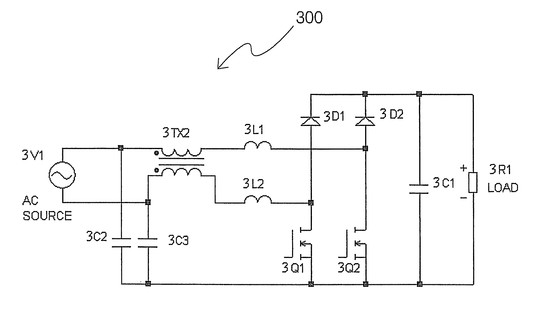
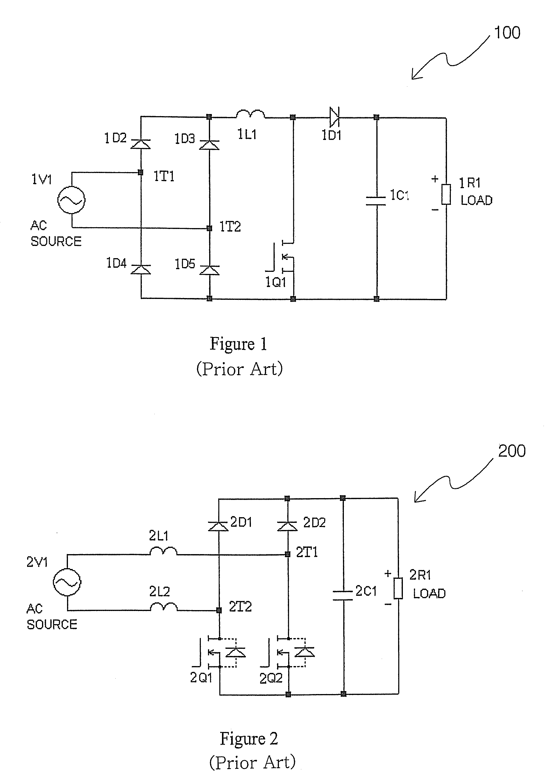
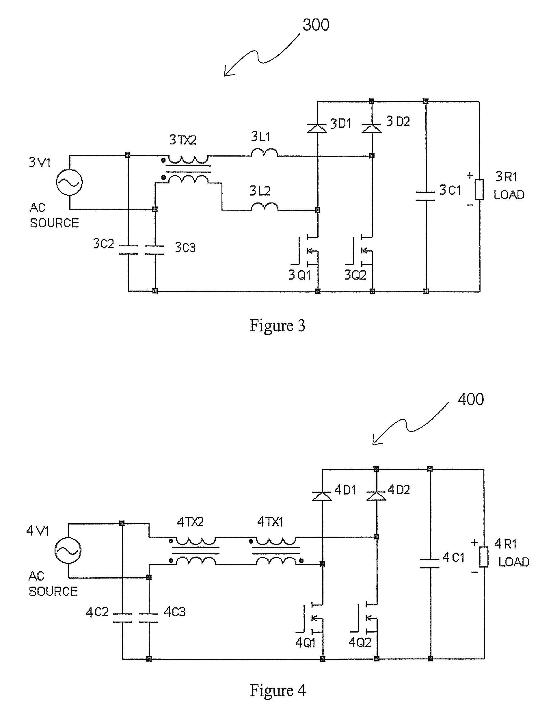
[0009]According to another embodiment, a method for power factor correction in an AC power current carrying system is disclosed. The method includes receiving and storing energy from an incoming AC power supply in a first and second boost choke and presenting a relatively high input impedance to the boost chokes. The method also includes rectifying the incoming AC power supply using a combination of a pair of rectifier diodes and semiconductor switches and controlling a duty cycle of the semiconductor switches. The method also includes bypassing an input line of the AC power supply to an output terminal with a relatively low impedance so that a small high frequency potential difference exists between the input line of the AC power supply and said output terminal to reduce common mode conducted electromagnetic interference (EMI).

Problems solved by technology

Switching mode power supplies can generate high frequency noise which travels over the power lines and interferes with the operation of computers and other electronic devices connected to the power lines.
EMI in the environment induces or couples electrical noise into the power lines.
EMI generated by the noise signals is generally an unwanted disturbance that may affect an electrical circuit.
The disturbance can interrupt, obstruct, or otherwise degrade or limit the effective performance of the circuit.

Method used


Image

  • Bridgeless boost PFC circuits and systems with reduced common mode EMI
  • Bridgeless boost PFC circuits and systems with reduced common mode EMI
  • Bridgeless boost PFC circuits and systems with reduced common mode EMI

Examples


Embodiment Construction

[0020]Example embodiments will now be described more fully with reference to the accompanying drawings

[0021]Example embodiments are provided so that this disclosure will be thorough, and will fully convey the scope to those who are skilled in the art. Numerous specific details are set forth such as examples of specific components, devices, and methods, to provide a thorough understanding of embodiments of the present disclosure. It will be apparent to those skilled in the art that specific details need not be employed, that example embodiments may be embodied in many different forms and that neither should be construed to limit the scope of the disclosure. In some example embodiments, well-known processes, well-known device structures, and well-known technologies are not described in detail.

[0022]The terminology used herein is for the purpose of describing particular example embodiments only and is not intended to be limiting. As used herein, the singular forms “a”, “an” and “the” m...


PUM


Abstract

According to one example embodiment, a bridgeless boost power factor correction (PFC) system includes a first input for connection to a first line of an alternating current (AC) source and a second input for connection to a second line of the AC source. The PFC system includes an output for delivering an output of the bridgeless boost PFC system, a first boost choke coupled to the first input and a second boost choke coupled to the second input. A common mode choke is coupled between the first and second input and the first and second boost choke. A first X capacitor is coupled between the first input and the output and a second X capacitor coupled between the second input and the output.

Description

FIELD[0001]The present disclosure relates to the bridgeless boost power factor correction (PFC) circuits and systems. In particular, this disclosure relates to bridgeless boost PFC circuits and systems with reduced common mode electromagnetic interference (EMI).BACKGROUND[0002]Switching mode power supplies can generate high frequency noise which travels over the power lines and interferes with the operation of computers and other electronic devices connected to the power lines. EMI in the environment induces or couples electrical noise into the power lines. EMI generated by the noise signals is generally an unwanted disturbance that may affect an electrical circuit. The disturbance can interrupt, obstruct, or otherwise degrade or limit the effective performance of the circuit.[0003]Electrical noise is classified into two types according to the conduction mode. Electrical noise which comes in one power line wire and returns to the noise source through the other power line wire is ter...

Claims


Application Information

Patent Timeline
Patent Type & Authority Patents(United States)
IPC IPC(8): H02M1/12H02M7/00
CPCH02M1/44H02M1/4225Y02B70/126H02M1/126Y02B70/10Y02P80/10H02M1/0085
Inventor WILDASH, KEVIN D.
Owner ASTEC INT LTD
Why Eureka
Try Eureka