Catadioptric projection objective

a technology of catadioptric projection and objective, which is applied in the field of catadioptric projection objective for microlithography, can solve the problems of increasing the local radiation load of the lens arranged in the vicinity, increasing the resolution, and typical lens materials such as quartz or calcium fluoride, for example, showing damage due to irradiation, etc., and achieving increased resolution, increased throughput, and greater damage

Active Publication Date: 2012-10-30
CARL ZEISS SMT GMBH
View PDF37 Cites 0 Cited by
  • Summary
  • Abstract
  • Description
  • Claims
  • Application Information

AI Technical Summary

Benefits of technology

[0008]The doubled passage through the lenses adjacent to the concave mirror, the increase in the light power of the light source for increasing the throughput, the illumination of the entrance pupil and thus of the lenses adjacent to the concave mirror with illumination poles having a small extent, the use of deep UV light and the use of lens materials which can be damaged on account of the radiation loading have the effect that, in the case of this class of projection objectives, the lenses of the second partial objective which are arranged adjacent to the concave mirror are particularly at risk of being damaged by the operation of the projection exposure apparatus.
[0009]It is an object of the invention, then, to specify a catadioptric projection objective, a projection exposure apparatus comprising an illumination system and a catadioptric projection objective, and also a method for operating a projection exposure apparatus comprising an illumination system and a catadioptric projection objective, which, despite these boundary conditions, enable the lithographic production of semiconductor components with uniform quality.
[0022]In general, in the case of this class of projection objectives, the concave mirror has greater bending in comparison with the adjacent lens surface for the purpose of better correction of the image field curvature. This has the effect that the distance between the concave mirror and the adjacent lens surface is the smallest at the edge of the concave mirror. The spatial separation of a light beam on the outgoing path and on the return path is therefore particularly difficult on the adjacent lens surface when the light beam is aimed at the edge of the concave mirror, that is to say originates from an illumination pole at the edge of the entrance pupil. In order then to reduce the radiation loading on the lens surface—facing the concave mirror—of the lens adjacent to the concave mirror, the distance between the concave mirror and the lens adjacent to the concave mirror is chosen to be so large that all rays which emerge from an illumination pole in the entrance pupil and intersect the object plane at a central object point within the object field pass through that surface of the lens which faces the concave mirror on the light path towards the concave mirror and on the light path away from the concave mirror in spatially separated regions, wherein the illumination pole is arranged at the edge of the entrance pupil, and wherein the extent of the illumination pole in the y-direction is greater than 2% of the pupil radius of the entrance pupil. An illumination pole is arranged at the edge of the entrance pupil when the illumination pole at a maximum distance of 5% of the pupil radius at the entrance pupil from the edge of the entrance pupil has an intensity of at least 10% relative to the maximum intensity of the illumination pole. The extent of an illumination pole in the y-direction is determined by taking a section through the intensity profile of the illumination pole along the y-direction and determining the distance between the two 10% points, at which the intensity profile, proceeding from a maximum value, has fallen to a value of 10% relative to the maximum value. In this case, the extent of the illumination pole in the y-direction represents the maximum possible value for the distance between the 10% points for this illumination pole. The central object point is understood to mean an object point which lies on the straight line of intersection between the object plane and the plane of symmetry and is at the same distance from the upper and lower object field edges in the y-direction.
[0032]In one embodiment of the invention, the concave mirror of the second partial objective has a diameter of the optically utilized region of less than 260 mm. What is thereby achieved is that the concave mirror can be produced and qualified with reasonable outlay.
[0036]The reduction of the radiation loading of the lenses of the second partial objective which are passed through twice makes it possible to provide a projection exposure apparatus which permits the entrance pupil of the projection objective to be illuminated with at least one illumination pole whose maximum extent in the y-direction is less than 8% of the pupil radius of the entrance pupil of the projection objective. In this case, the projection exposure apparatus for microlithography comprises an illumination system, which provides at least one illumination mode, and a catadioptric projection objective, which images an object field in an object plane onto an image field in an image plane, comprising

Problems solved by technology

Consequently, the increase in the resolution leads to an increase in the local radiation loading of the lenses arranged in the vicinity of the concave mirror.
In this wavelength range, typical lens materials such as quartz or calcium fluoride, for example, exhibit damage on account of the irradiation.
Moreover, the irradiation can lead to a transmission loss owing to the formation of color centers.
The effects mentioned depend in part non-linearly on the irradiance, such that a doubling of the radiation loading can lead to significantly greater damage, as would be the case for effects linearly dependent on the irradiance.
The doubled passage through the lenses adjacent to the concave mirror, the increase in the light power of the light source for increasing the throughput, the illumination of the entrance pupil and thus of the lenses adjacent to the concave mirror with illumination poles having a small extent, the use of deep UV light and the use of lens materials which can be damaged on account of the radiation loading have the effect that, in the case of this class of projection objectives, the lenses of the second partial objective which are arranged adjacent to the concave mirror are particularly at risk of being damaged by the operation of the projection exposure apparatus.

Method used


Image

  • Catadioptric projection objective
  • Catadioptric projection objective
  • Catadioptric projection objective

Examples


Embodiment Construction

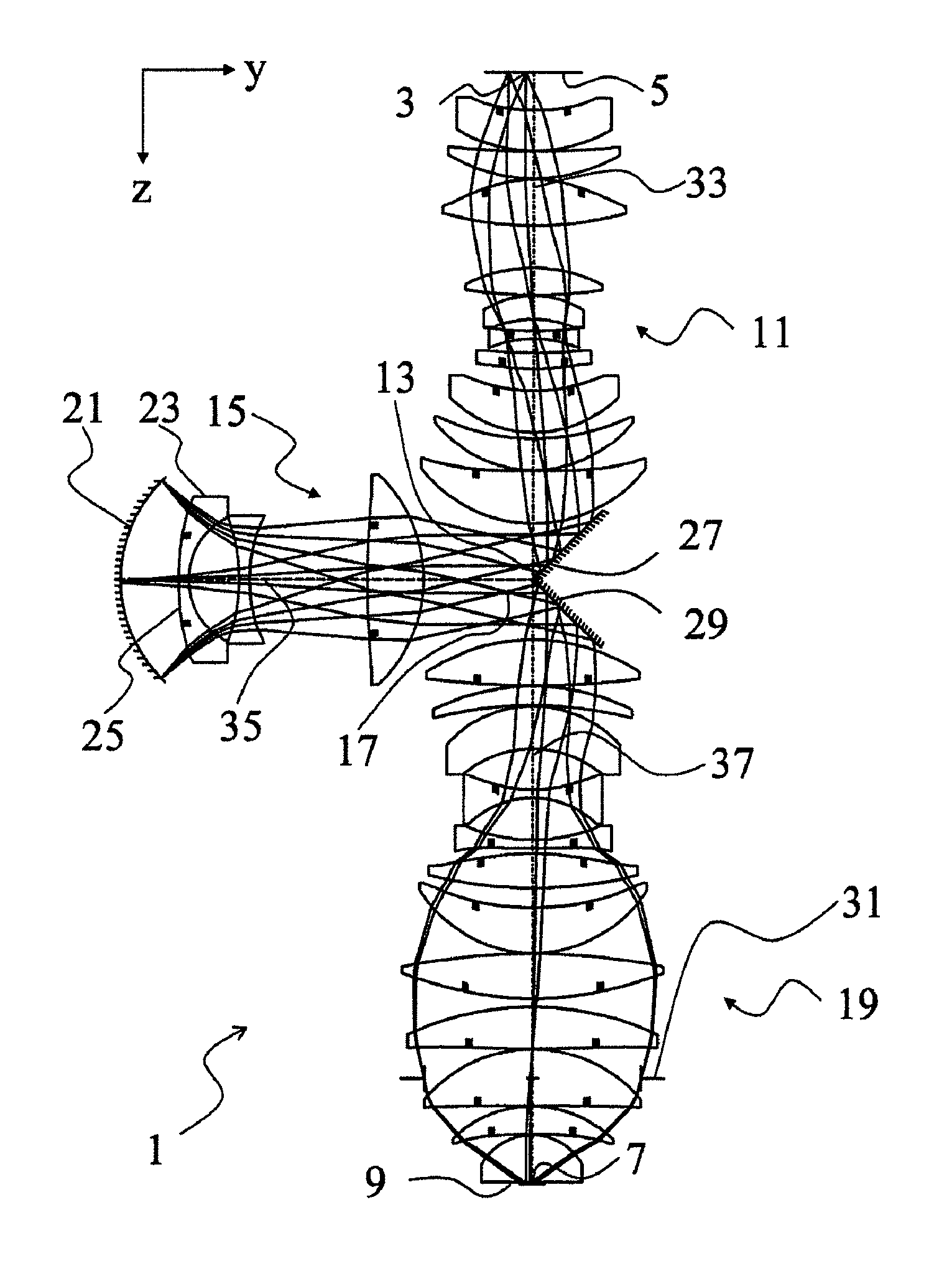
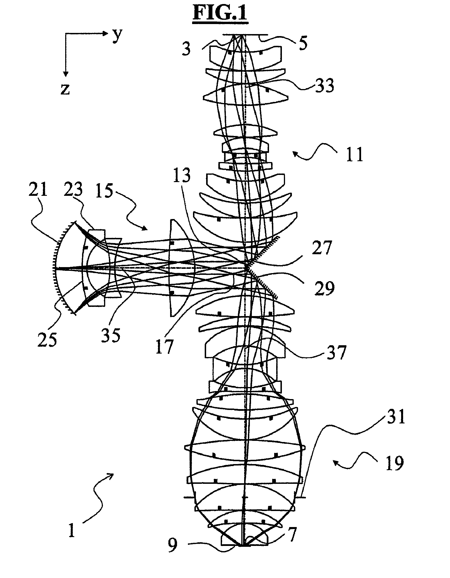
[0067]FIG. 1 shows a lens section of a catadioptric projection objective 1. The optical data for the projection objective 1 are compiled in Table 1. The lens materials used are, in all the lenses apart from the lens adjacent to the image plane, quartz (SiO2), having a refractive index of n=1.5603261 at a wavelength of 193.306 nm and, in the lens adjacent to the image plane, spinel (MgAl2O4) having a refractive index of n=1.91 at a wavelength of 193.306 nm. The aspherical surfaces can be described by the following sagitta formula:

[0068]p⁡(h)=1R⁢h21+1-(1+K)⁢(1R)2⁢h2+∑k=1⁢⁢Ck⁢h2⁢k+2

[0069]In this case, p represents the axial distance in [mm] of the aspherical surface from a plane—perpendicular to the optical axis—through the vertex of the aspherical surface in the case of the radial distance h in [mm], R represents the vertex radius in [mm], K represents the conical constant and Ck represents the individual aspherical constants of the order k in

[0070]

TABLE 2Aperture rayxf [mm]yf [mm]xpy...


PUM


Abstract

Catadioptric projection objective (1) for microlithography for imaging an object field (3) in an object plane (5) onto an image field (7) in an image plane (9), including a first partial objective (11) imaging the object field onto a first real intermediate image (13), a second partial objective (15) imaging the first intermediate image onto a second real intermediate image (17) and a third partial objective (19) imaging the second intermediate image onto the image field (7). The second partial objective (15) has exactly one concave mirror (21) and at least one lens (23). The minimum distance between an optically utilized region of the concave mirror (21) and an optically utilized region of a surface (25)—facing the concave mirror—of a lens (23) adjacent to the concave mirror is greater than 10 mm.

Description

[0001]The following disclosure is based on German Patent Application No. DE 102009045217.6, filed on Sep. 30, 2009, which is incorporated into this application by reference.FIELD OF AND BACKGROUND OF THE INVENTION[0002]The invention relates to a catadioptric projection objective for microlithography for imaging an object field in an object plane onto an image field in an image plane comprising three partial objectives, as well as to a projection exposure apparatus for microlithography comprising an illumination system for providing at least one illumination mode and a catadioptric projection objective for imaging an object field in an object plane onto an image field in an image plane comprising three partial objectives, and also to a method for operating a projection exposure apparatus for microlithography comprising an illumination system for providing at least one illumination mode and a catadioptric projection objective for imaging an object field in an object plane onto an imag...

Claims


Application Information

Patent Timeline
Patent Type & Authority Patents(United States)
IPC IPC(8): G03B27/54G03B27/42
CPCG02B13/143G03F7/70225G02B17/0892G02B17/0812G03F7/20G03B17/08G03B13/00
Inventor EPPLE, ALEXANDERGRUNER, TORALFMUELLER, RALF
Owner CARL ZEISS SMT GMBH
Why Eureka
Try Eureka