Active damping of high speed scanning probe microscope components

a scanning probe and component technology, applied in the direction of instruments, shock absorbers, force/torque/work measurement apparatus, etc., can solve the problems of sample and/or probe damage, actuators may not be able to move either the sample or the base of the cantilever quickly, and the accuracy of atomic force microscope sample characterization is often limited, so as to reduce cost and complexity, simplify the design and implementation of active damping, and enhance performance

Active Publication Date: 2012-11-06
OXFORD INSTR ASYLUM RES INC +1
View PDF170 Cites 22 Cited by
  • Summary
  • Abstract
  • Description
  • Claims
  • Application Information

AI Technical Summary

Benefits of technology

[0035]A characteristic of the technique and physical implementation of it discussed here is that both the sensing and actuation can be incorporated into a single device so that the design and implementation of the active damping is simplified and cost and complexity is reduced.
[0036]This technique is useful for damping relative vibrations between different points of the instrument.
[0037]An advantage of the instrumentation

Problems solved by technology

Accurate characterization of a sample by an atomic force microscope is often limited by the ability of the atomic force microscope to move the base of the cantilever vertically in the Z direction relative to the sample surface at a rate sufficient to characterize the sample accurately while scanning in either the X or Y direction.
In practice, this means that the actuator may not be able to move either the sample or the base of the cantilever rapidly enough to track the surface accurately.
This can lead to either the sample and/or probe being damaged, or to the reproduction of the surface topography being less accurate.
However, at some point, the z-actuator will begin to resonate and that resonant motion will create parasitic oscillations in the actuator support structure and even change the phase of the response of the actuator to inputs.
These parasitic oscillations and phase changes reduce the performance of the instrument and the quality of the images and other data produced.
This increased extension, however, results in an increased reaction force on the support structure 3.
However, large variations in the error parameter using this technique may have detrimental effects, including but not limited to tip dulling or damage and sample damage.
The actuated cantilever approach raises some difficulties.
Tuning two feedback loops is significantly more time consuming and problematic than tuning a single loop.
Combining the final data to obtain an accurate characterization of the sample

Method used


Image

  • Active damping of high speed scanning probe microscope components
  • Active damping of high speed scanning probe microscope components
  • Active damping of high speed scanning probe microscope components

Examples


Embodiment Construction

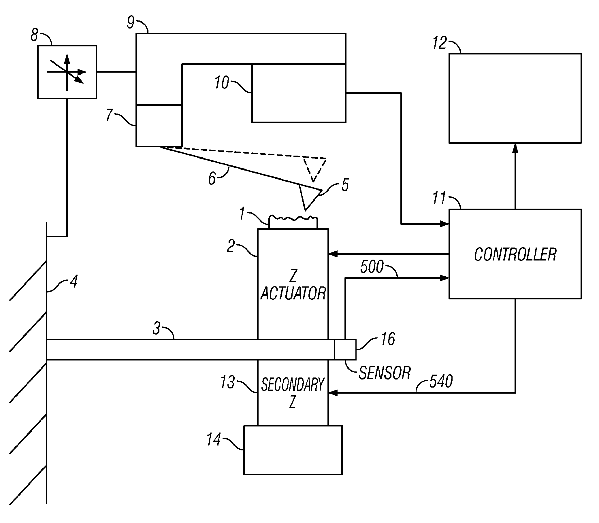
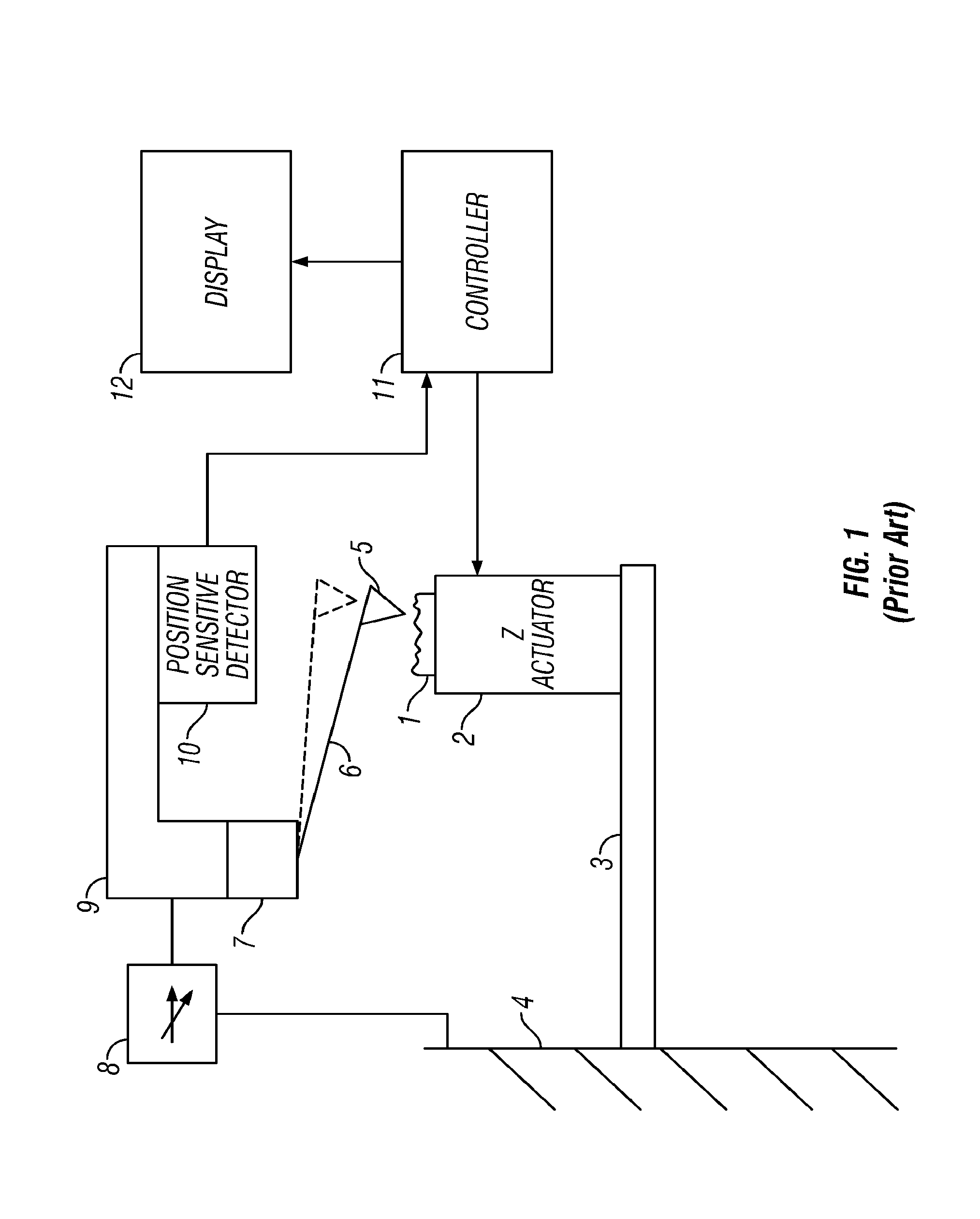
[0051]Cantilever-based instruments include such instruments as atomic force microscopes, molecular force probe instruments (1D or 3D), high-resolution profilometers and chemical or biological sensing probes. The embodiment describes atomic force microscopes (AFMs). The embodiments encompass these devices as well as any other metrology instrument that can be used in nanoscale applications.

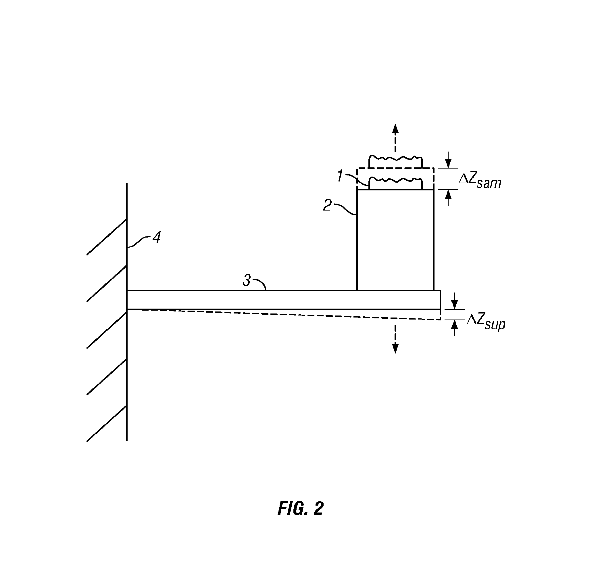
[0052]According to an embodiment, any mechanical oscillations in the atomic force microscope support structure is measured. A damping force is applied with the goal of preventing the parasitic oscillations from degrading performance. Active damping of the support structure enables extremely accurate scanning of even the smallest surface features and even at high scan speeds where conventional actuators suffer from poor performance.

[0053]Embodiments can be used with cantilever-based instruments, that is, an apparatus having a probe for characterizing a sample. The apparatus may have an x-actuator, a ...


PUM


Abstract

A technique for actively damping internal vibrations in a scanning probe microscope is disclosed. The excitation of various mechanical movements, including resonances, in the mechanical assembly of an SPM can adversely effect its performance, especially for high speed applications. An actuator is used to compensate for the movements. The actuator may operate in only the z direction, or may operate in other directions. The actuator(s) may be located at positions of antinodes.

Description

CROSS-REFERENCE TO RELATED APPLICATIONS[0001]This application which claims priority to U.S. Provisional Application No. 60 / 776,385, filed on Feb. 23, 2006. The disclosure of the prior application is considered part of (and is incorporated by reference in) the disclosure of this application.BACKGROUND[0002]An atomic force microscope is a device used to produce images of surface topography (and other sample characteristics) based on information obtained from rastering a sharp probe on the end of a cantilever relative to the surface of a sample. Deflections of the cantilever, or changes in its oscillation which are detected while rastering correspond to topographical (or other) features of the sample. Deflections or changes in oscillation are typically detected by an optical lever arrangement whereby a light beam is directed onto a cantilever in the same reference frame as the optical lever. The beam reflected from the cantilever illuminates a position sensitive detector (PSD). As the ...

Claims


Application Information

Patent Timeline
IPC IPC(8): G01Q30/20G01D11/10G01Q10/06
CPCB82Y35/00F16F7/1011G01L5/0061G01Q70/04G01L5/0038G01Q10/065G01Q10/04G01Q10/06G01Q60/24
Inventor PROKSCH, ROGER
Owner OXFORD INSTR ASYLUM RES INC
Why Eureka
Try Eureka