Elimination of fractional N boundary spurs in a signal synthesizer

a signal synthesizer and fractional n boundary spur technology, applied in oscillator generators, pulse automatic control, electrical equipment, etc., can solve problems such as undesirable devices, boundary spur phenomenon, and reduce the usefulness of the synthesizer system, and achieve the effect of elimination of boundary value spurs

Active Publication Date: 2012-11-06
ANRITSU CO
View PDF8 Cites 22 Cited by
  • Summary
  • Abstract
  • Description
  • Claims
  • Application Information

AI Technical Summary

Benefits of technology

[0006]Embodiments of the present invention enable elimination of boundary value spurs for a Fractional N type frequency synthesizer. Elimination of the boundary spurs enables the Fractional N type synthesizer to be more readily used as a portable synthesizer over a wide frequency range.
[0010]For circuitry to accomplish embodiments of the present invention, in a first embodiment two separate time base references are provided within a single phase locked loop. A switch separately connects the different time bases to the phase locked loop in the signal synthesizer. Either calculations or a lookup table are used to determine when boundary spurs occur using the first time base. The second time base is selected to prevent any overlap of boundary spurs. The switch and frequency selections are then controlled to connect to the second time base where boundary spurs occur using the first time base to effectively eliminate the spurs.

Problems solved by technology

The size and power requirements for synthesizers using the first and second techniques, Direct Synthesis and DDS respectively, make those devices undesirable for use as a portable component for field testing over a desired test frequency range.
A major drawback of this Fractional N approach, however, is a phenomenon called boundary spurs.
The pushed out spurs still, however, imply that a range of fractional values cannot be used, reducing the usefulness of the synthesizer system.

Method used


Image

  • Elimination of fractional N boundary spurs in a signal synthesizer
  • Elimination of fractional N boundary spurs in a signal synthesizer
  • Elimination of fractional N boundary spurs in a signal synthesizer

Examples


Embodiment Construction

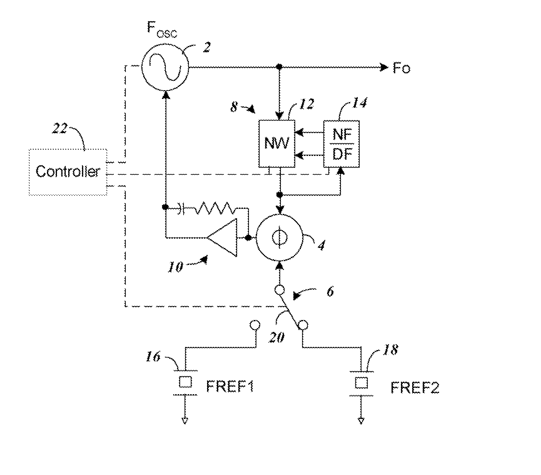
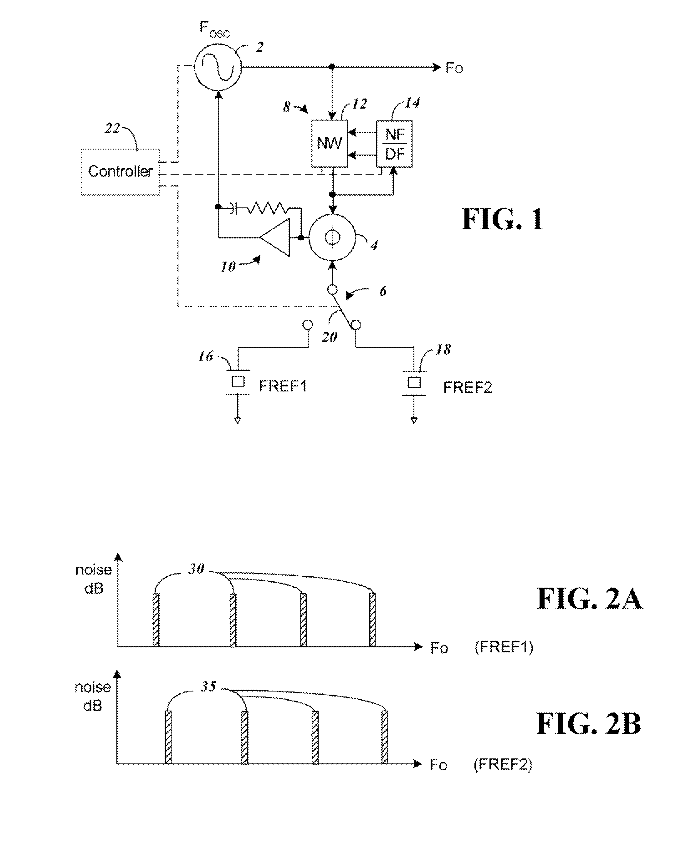
[0018]FIG. 1 shows a block diagram of components of a Fractional N Delta Sum Phase Locked Loop with components according to one embodiment of the present invention that allows selection between two separate time bases 16 and 18. By providing a switch 20 to selectively connect one of the time bases 16 and 18, and by appropriately choosing the operating frequency of the time bases 16 and 18 boundary spurs can be avoided.

[0019]The phase locked loop of FIG. 1 is formed from a variable frequency signal source 2, phase detector 4, time base reference 6, frequency divider 8, and integrator 10. In operation, the phase locked loop phase detector 4 receives inputs from the time base frequency reference 6 and the signal source 2 through frequency divider 8. The output of the phase detector 4 through integrator 10 provides a voltage control signal to the signal source 2 to assure it is phase aligned with the time base reference 6.

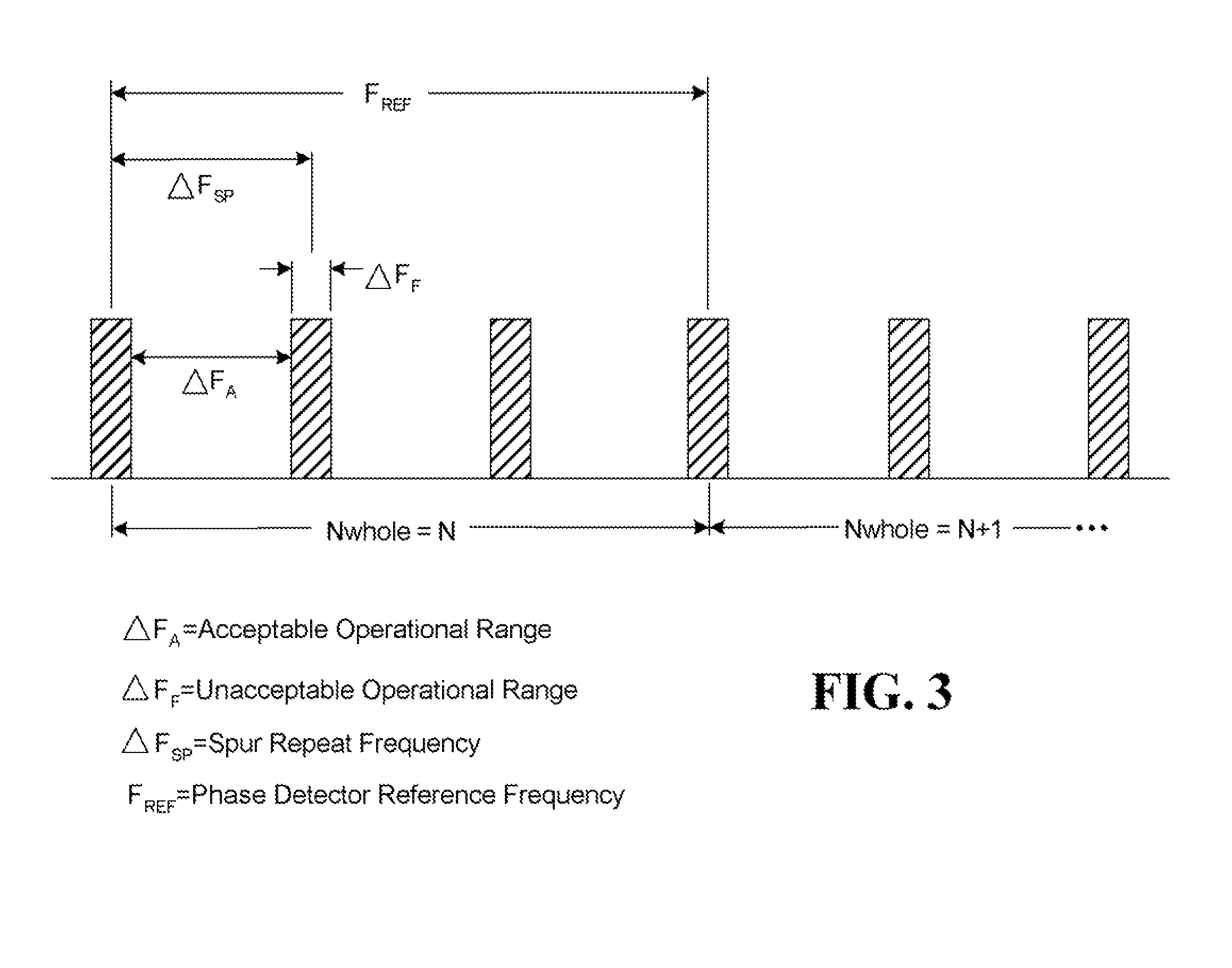
[0020]For a fractional N type phase locked loop, the frequency di...


PUM


Abstract

A portable frequency synthesizer is provided with fine tuning over a broad bandwidth using a Fractional N type Delta Sum Phase Locked Loop circuit that enables elimination of boundary value spurs. In the system, frequencies where spurs occur are calculated to define a region of fractional N values that cannot be used with a first time base. To avoid the boundary spurs, a second time base reference is selected that can generate boundary spurs that do not overlap with the first time base. Circuitry is provided to select the appropriate time base and the fractional N values to generate desired output frequencies throughout the synthesizer range while avoiding the boundary spurs.

Description

BACKGROUND[0001]1. Technical Field[0002]The present invention relates to a fine resolution signal synthesizer that operates over a continuous frequency bandwidth using a Fractional N Delta Sum Phase Locked Loop.[0003]2. Related Art[0004]Traditional fine resolution synthesizers are made using one of three different techniques. The first is a Direct Synthesis technique that includes a phase locked loop that provides frequency adjustment using one of a sum, difference, multiply or a divide component. The second is a Direct Digital Synthesis (DDS) technique that creates and varies the output frequency using digital techniques. The third is a Delta Sigma approach, also know as a Fractional N Delta Sum Phase Locked Loop.[0005]The size and power requirements for synthesizers using the first and second techniques, Direct Synthesis and DDS respectively, make those devices undesirable for use as a portable component for field testing over a desired test frequency range. The third technique, t...

Claims


Application Information

Patent Timeline
Patent Type & Authority Patents(United States)
IPC IPC(8): H03B21/00
CPCH03B21/00H03L7/1976H03L7/23
Inventor BRADLEY, DONALD ANTHONY
Owner ANRITSU CO
Why Eureka
Try Eureka