Unlock instant, AI-driven research and patent intelligence for your innovation.

Computer architecture and method of operation for multi-computer distributed processing having redundant array of independent systems with replicated memory and code striping

a distributed processing and computer technology, applied in the field of computer architecture and method of operation for multi-computer distributed processing, can solve the problems of inability to scale over “commodity” (or mass produced) computers and networks, invariably increasing the administrative overhead of machines, and extremely expensive not only to manufacture but to administer single system image concepts

Active Publication Date: 2012-11-20
WARATEK LTD
View PDF86 Cites 11 Cited by
  • Summary
  • Abstract
  • Description
  • Claims
  • Application Information

AI Technical Summary

Benefits of technology

"The present invention is about a system and method for replicating computer programs and data across multiple computers. The system includes multiple computers connected by a network, each computer having its own local memory and processor. The method involves replicating memory data from one computer to another, updating the replicated data when there are changes, and ensuring that the replicated data remains consistent between the computers. The system also allows for the simultaneous updating of replicated memory locations between the computers. The invention provides a way to efficiently distribute and update computer programs and data across multiple computers."

Problems solved by technology

The bus 4 suffers from a number of problems including so called bus “queues” formed by units wishing to gain an access to the bus, contention problems, and the like.
These problems can, to some extent, be alleviated by various stratagems including cache memory; however, such stratagems invariably increase the administrative overhead of the machine 1.
Although super computers have been technically successful in achieving high computational rates, they are not commercially successful in that their inherent complexity makes them extremely expensive not only to manufacture but to administer.
In particular, the single system image concept has never been able to scale over “commodity” (or mass produced) computers and networks.
In particular, the Single System Image concept has only found practical application on very fast (and hence very expensive) computers interconnected by very fast (and similarly expensive) networks.
Firstly, it is a difficult job to partition the application and this must be done manually.
Secondly, communicating data, partial results, results and the like over the network 14 is an administrative overhead.
Thirdly, the need for partitioning makes it extremely difficult to scale upwardly by utilising more machines since the application having been partitioned into, say three, does not run well upon four machines.
Fourthly, in the event that one of the machines should become disabled, the overall performance of the entire system is substantially degraded.
This approach does operate, is scalable and mainly suffers from the disadvantage that it is difficult to administer the network.
In either case, however, there is no equivalent “clean up” or deletion routine to delete an object or class (or other asset) once it is no longer required.
Unfortunately, conventional computing systems, architectures, and operating schemes do not provide for computing environments and methods in which an application program can operate simultaneously on an arbitrary plurality of computers where the environment and operating scheme ensure that the abovementioned memory management, initialization, clean up and synchronization procedures operate in a consistent and coordinated fashion across all the computing machines.
Furthermore, conventional computing systems, architectures, and operating schemes do not provide for computing environments and methods which provide for a redundant array of independent systems or for code-striping in such systems.

Method used


Image

  • Computer architecture and method of operation for multi-computer distributed processing having redundant array of independent systems with replicated memory and code striping
  • Computer architecture and method of operation for multi-computer distributed processing having redundant array of independent systems with replicated memory and code striping
  • Computer architecture and method of operation for multi-computer distributed processing having redundant array of independent systems with replicated memory and code striping

Examples


first embodiment

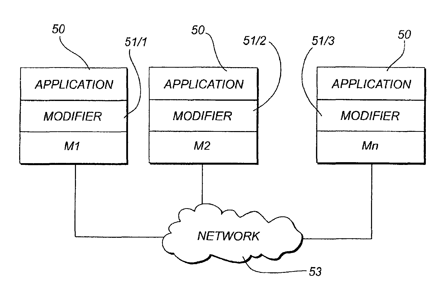
[0391]In the first embodiment, a particular machine, say machine M2, loads the asset (such as class or object) inclusive of memory manipulation operation(s), modifies it, and then loads each of the other machines M1, M3, . . . , Mn (either sequentially or simultaneously or according to any other order, routine or procedure) with the modified object (or class or other asset or resource) inclusive of the new modified memory manipulation operation. Note that there may be one or a plurality of memory manipulation operations corresponding to only one object in the application code, or there may be a plurality of memory manipulation operations corresponding to a plurality of objects in the application code. Note that in one embodiment, the memory manipulation operation(s) that is (are) loaded is binary executable object code. Alternatively, the memory manipulation operation(s) that is (are) loaded is executable intermediary code.

[0392]In this arrangement, which may be termed “master / slave...

second embodiment

[0655]In a second embodiment illustrated in FIG. 71, the machine, say machine M7, wishing to acquire the lock repeats steps 31 and 32 of FIG. 66 (illustrated as steps 81 and 82 in FIG. 71). However, machine M7 then carries out step 83 in FIG. 71 by sending a “DO YOU HOLD LOCK” request, which names the desired object, asset or resource to be locked, to all the other machines M1, M2, . . . M6, M8, . . . Mn and X. Machine M7 then waits for a short predetermined period to see if any positive reply is received. If so, machine M7 then waits for a relatively long predetermined period and then retries by sending out another request (as indicated by steps 84, 85 and 86 of FIG. 71).

[0656]In the alternative, if no positive reply is received within the short predetermined period, machine M7 then instructs machine X to confer the lock upon it (as indicated by steps 84, 85 and 87 in FIG. 71). Once machine X confers the lock, machine M7 resumes normal processing.

[0657]The corresponding actions tak...


PUM


Abstract

Computers and other computing machines and information appliances having a modified computer architecture and program structure which enables the operation of an application program concurrently or simultaneously on a plurality of computers interconnected via a communications link or network using a special distributed runtime (DRT), and that provides for a redundant array of independent computing systems that include computer code distribution using code-striping onto the plurality of the computers or computing machines. A redundant array of independent computing systems operating in concert and code-striping features.

Description

CROSS-REFERENCE TO RELATED APPLICATIONS[0001]This application claims benefit under 35 USC 119(e) to the following U.S. Provisional Applications: 60 / 922,251 filed Apr. 6, 2007; 60 / 878,175 filed Dec. 29, 2006; 60 / 998,090 filed Oct. 5, 2007; 60 / 998,085 filed Oct. 5, 2007; 61 / 008,529 filed Dec. 19, 2007; 61 / 008,530 filed Dec. 19, 2007; 61 / 008,531 filed Dec. 19, 2007; 61 / 008,526 filed Dec. 19, 2007; 61 / 008,527 filed Dec. 19, 2007; 61 / 008,528 filed Dec. 19, 2007; 61 / 008,523 filed Dec. 19, 2007; 61 / 008,524 filed Dec. 19, 2007; 61 / 008,525 filed Dec. 19, 2007; 61 / 008,535 filed Dec. 19, 2007; 61 / 008,538 filed Dec. 19, 2007; 61 / 008,522 filed Dec. 19, 2007; 61 / 008,544 filed Dec. 19, 2007; 61 / 008,541 filed Dec. 19, 2007; 61 / 008,542 filed Dec. 19, 2007; 61 / 008,539 filed Dec. 19, 2007; 61 / 008,518 filed Dec. 19, 2007; 61 / 008,543 filed Dec. 19, 2007; 61 / 008,536 filed Dec. 19, 2007; 61 / 008,545 filed Dec. 19, 2007; 61 / 008,537 filed Dec. 19, 2007; 61 / 008,540 filed Dec. 19, 2007; 61 / 008,532 filed Dec. 1...

Claims


Application Information

Patent Timeline
Patent Type & Authority Patents(United States)
IPC IPC(8): G06F12/00
CPCG06F9/526G06F9/546G06F11/1658G06F11/1666G06F11/2035G06F11/2028G06F11/203
Inventor HOLT, JOHN M.
Owner WARATEK LTD