Hypervelocity impact and time of arrival detection method and system

a detection method and time-of-arriving technology, applied in the direction of instruments, structural/machine measurement, elasticity measurement, etc., can solve the problems of excessive power consumption of high-speed data acquisition electronics, excessive vehicle resources required for the system, power consumption, mass, volume, etc., to achieve significant size, cost, and performance improvement

Active Publication Date: 2012-11-27
INVOCON
View PDF4 Cites 5 Cited by
  • Summary
  • Abstract
  • Description
  • Claims
  • Application Information

AI Technical Summary

Benefits of technology

[0014]The present hypervelocity impact detection and time of arrival (TOA) method and system utilizes multiple sensors that directly measure electrical pulse emissions generated by hypervelocity impacts on the detection surface, such as ballistic missile intercepts, micrometeoroids and orbital debris (MMOD) or other shock events, and time of arrival (TOA) position measurements for determining the precise impact location in the detection surface. The detection surface material is compressed differentially in such a way that the inherent equalization of the compressed electron density in one area of the impact is directed to the uncompressed area of the material and thus an electrical current flows until the redistribution of the electrical charge has been completed. This rapid redistribution of charge and the inherent current that results emits a radio frequency pulse that is induced into the conductive detection surface as well as radiated into the atmosphere. The present method and system provides significant size, cost, and performance improvements over conventional systems.

Problems solved by technology

Continuous damage detection and characterization for various structures has been an elusive goal due to the transitory nature of the detectable high-frequency signals.
However, the size, complexity, and power consumption of the necessary electronics to acquire, process, and store the resulting digital waveforms is often too large to be included in operational vehicles or structures.
Although these systems may be capable of detecting impact events, the vehicle resources required for the systems, such as power, mass, and volume, have been excessive.
The power consumption of these high-speed data acquisition electronics is significantly high.
To determine if the acquired data is a transitory event of interest, a digital circuit must process the acquired digital data in some way, which requires a significant amount of power and processor resources.
Continuously storing data to memory requires a significant amount of power.
Continuous damage detection and characterization for various structures has been an elusive goal due to the transitory nature of the detectable high-frequency signals.
However, the size, complexity, and power consumption of the necessary electronics to acquire, process, and store the resulting digital waveforms is often too large to be included in operational vehicles or structures.
Although capable of detecting impact events, the vehicle resources required for the systems such as power, mass, and volume, have been excessive.

Method used


Image

  • Hypervelocity impact and time of arrival detection method and system
  • Hypervelocity impact and time of arrival detection method and system
  • Hypervelocity impact and time of arrival detection method and system

Examples


Embodiment Construction

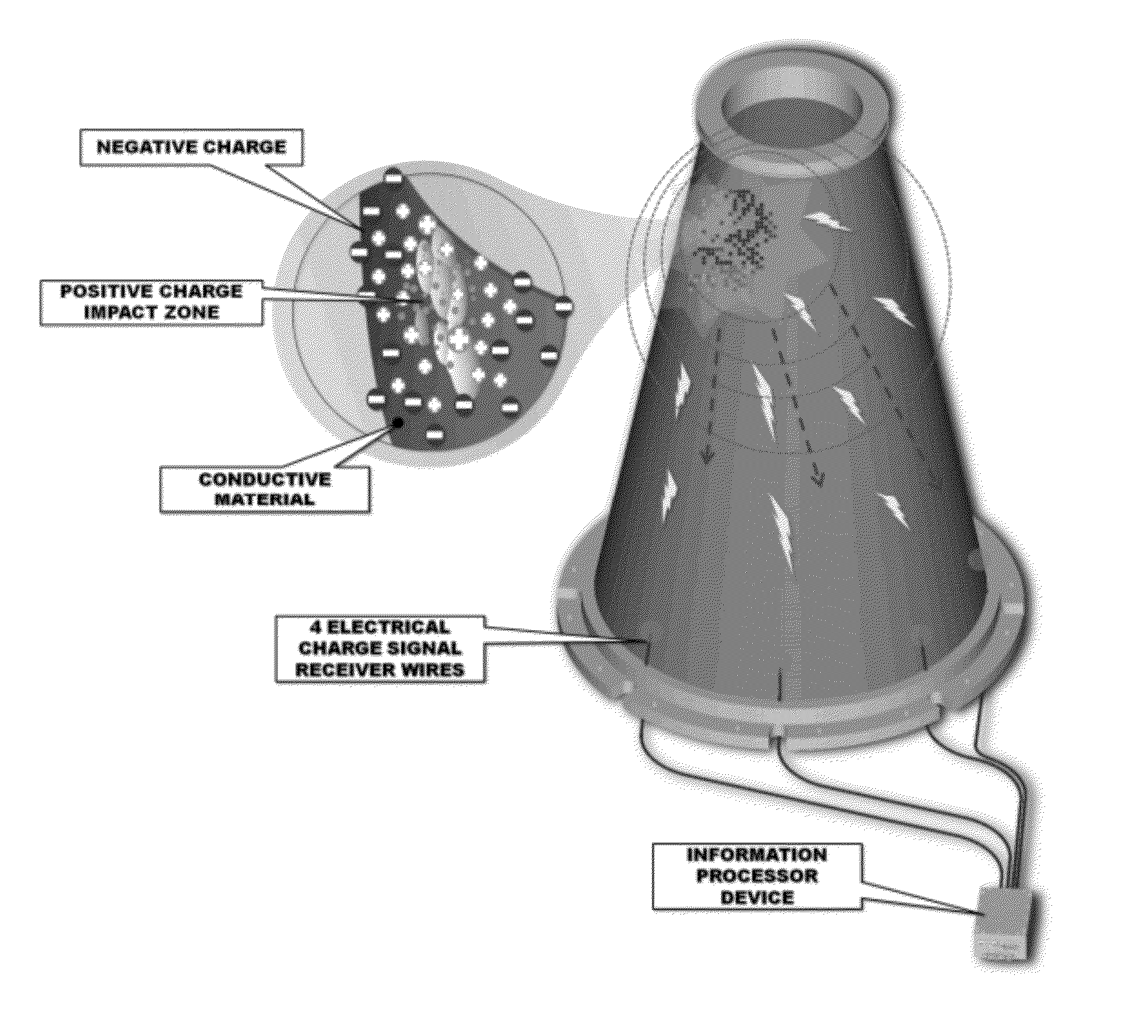
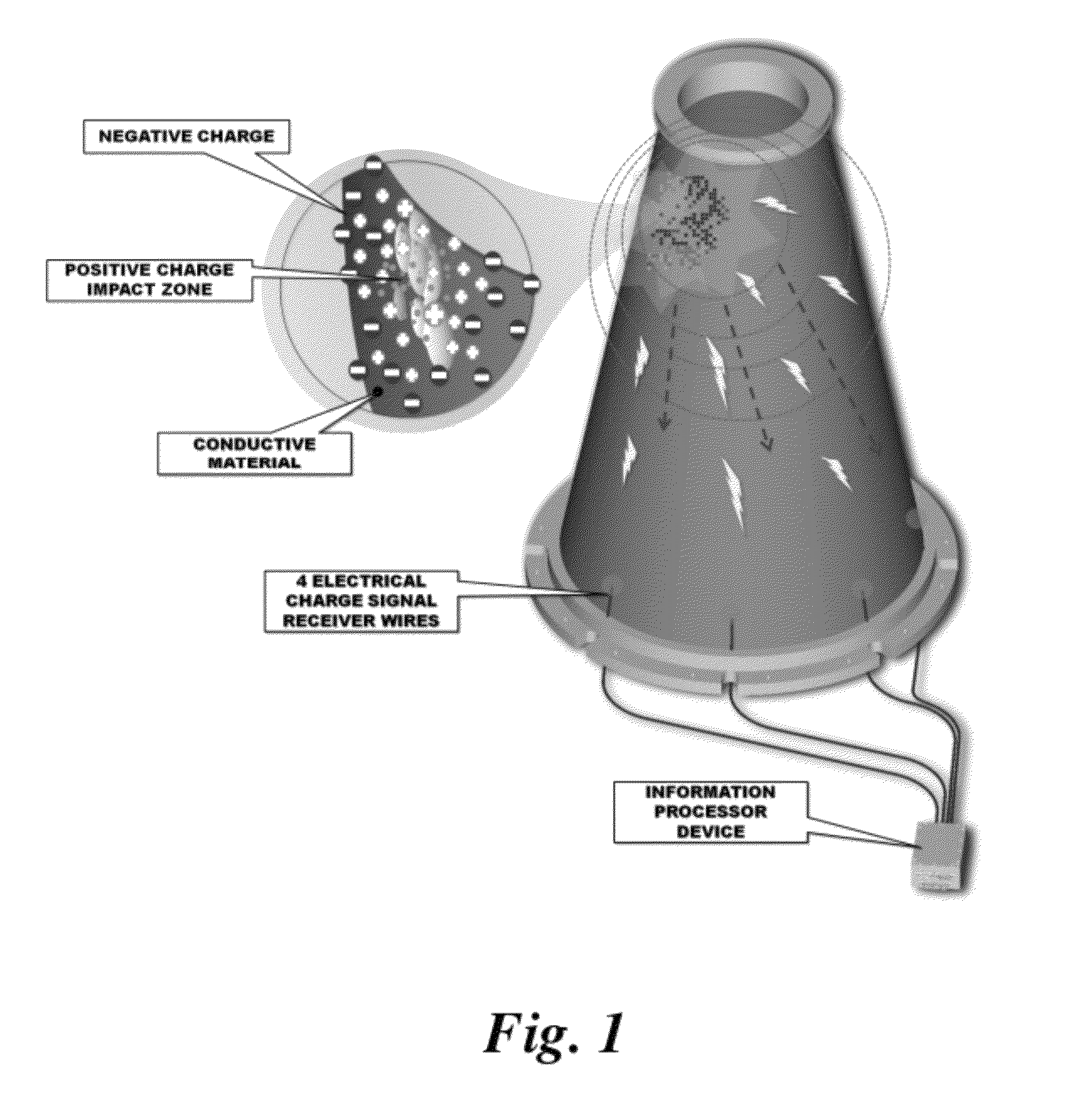
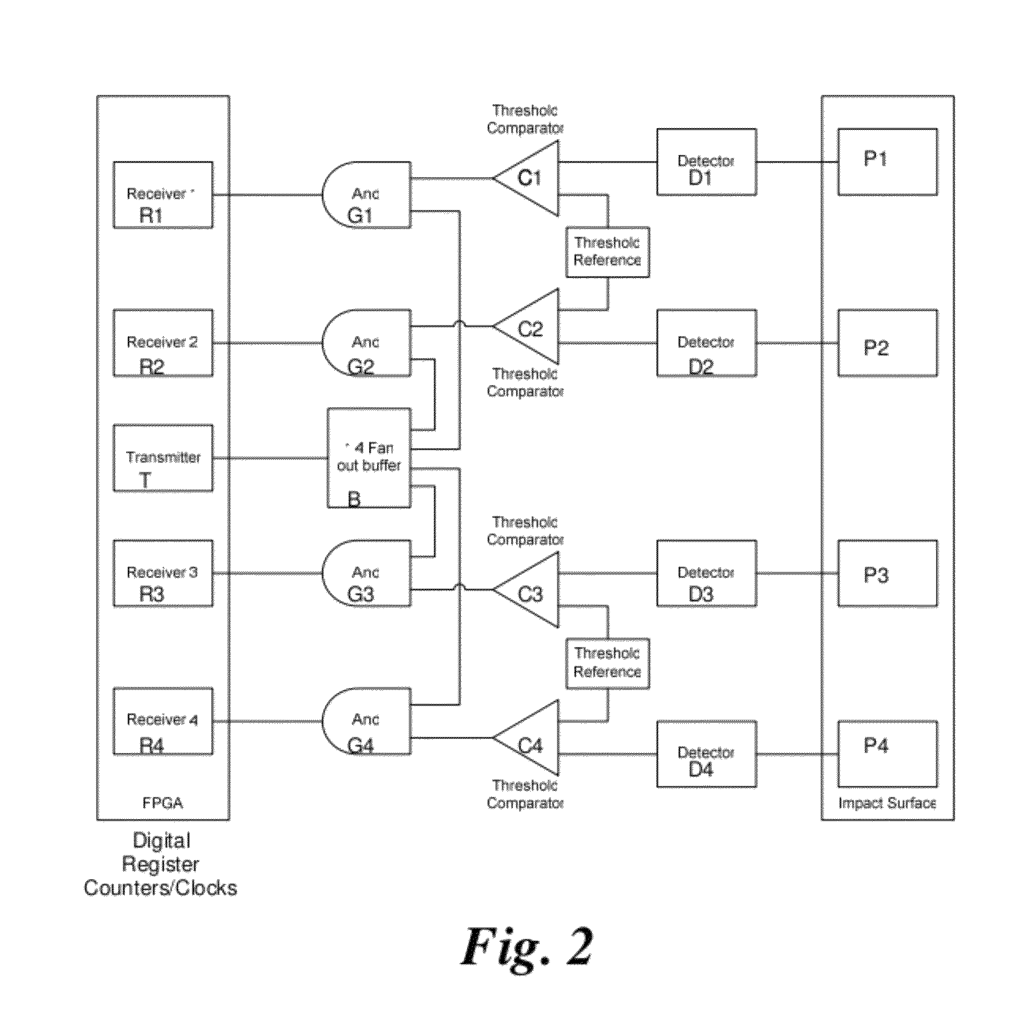
[0018]Based on data released by the Air Force Research Laboratory (AFRL) from impact testing performed in hypervelocity test chambers, hypervelocity impacts have been shown to generate detectable RF emissions. We have conducted tests at the NASA hypervelocity impact facility at Las Cruces, N. Mex. which has provided data on the frequency content and magnitude of such RF pulses If these RF emissions were to be sensed from multiple geometric locations on the breached surface the precise impact location could be determined by measuring the difference in Time of Arrival (TOA) of the generated signals. The measurement of this very small difference in TOA requires precise electronic timing to detect. For example, a path difference of 1 m corresponds to only 3.33 nanoseconds. Achieving centimeter position resolution requires picosecond timing accuracy. The present hypervelocity impact detection method and system provides a processing technique and system that allows the measurement of thes...


PUM


Abstract

A method and system for detecting hypervelocity impacts on a detection surface utilizes multiple sensors that directly measure electrical pulse radio frequency (RF) emissions generated by hypervelocity impacts on a detection surface and time of arrival (TOA) position measurements for determining the precise impact location on the detection surface. The detection surface material is compressed differentially in such a way that the inherent equalization of the compressed electron density in one area of the impact is directed to the uncompressed area of the material causing an electrical current that flows until the redistribution of the electrical charge has been completed and the rapid redistribution of charge and inherent current that results emits the radio frequency pulse that is induced into the detection surface.

Description

CROSS REFERENCE TO RELATED APPLICATIONS[0001]This application claims priority of U.S. Provisional Application Ser. No. 61 / 152,255, filed Feb. 13, 2009 the pendency of which is extended until February 15 under 35 U.S.C. 119(e)(3), and is a Continuation-In-Part of and claims priority of Non-provisional U.S. patent application Ser. No. 12 / 614,413, filed Nov. 7, 2009 claiming priority of provisional application 61 / 112,190 filed Nov. 7, 2008, which is a Continuation-In-Part and claims priority of Non-provisional U.S. patent application Ser. No. 12 / 383,062, filed Mar. 18, 2009, which claimed priority of U.S. Provisional Application Ser. No. 61 / 037,704, filed Mar. 18, 2008. Each of these identified prior applications is hereby incorporated by reference in its entirety.BACKGROUND OF THE INVENTION[0002]1. Field of the Invention[0003]This invention relates generally to methods and systems for determining the impact point and damage propagation in a detection surface, and more particularly to ...

Claims


Application Information

Patent Timeline
Patent Type & Authority Patents(United States)
IPC IPC(8): G01M7/00
CPCG01M7/00G01S5/06G01M5/0033G01M5/0091
Inventor KIEFER, KARL F.HEERMAN, DOUGPHILPOT, BRIANDEPALM, CHRISTOPHERROBERSON, GULNARAKRUG, ERIC
Owner INVOCON
Why Eureka
Try Eureka