Adaptive positive feed drilling system

a positive feed and drilling system technology, applied in the field of manufacturing, can solve the problems of increasing the quality of the hole, wasting considerable time in drilling the carbon fiber reinforced plastic layers at the slower speed, and limited positive feed drilling speed and/or feed rate of a stackup containing different layers

Active Publication Date: 2012-11-27
THE BOEING CO
View PDF23 Cites 770 Cited by
  • Summary
  • Abstract
  • Description
  • Claims
  • Application Information

AI Technical Summary

Problems solved by technology

Further, this type of drilling also may reduce the amount of heat applied to the object, which also may increase the quality of the hole.
Currently, positive feed drilling of a stackup containing different layers may be limited in speed and / or feed rate by the hardest layer in the stackup.
When performing drilling operations based on the speed and / or feed rate for the titanium layers, a considerable amount of time may be wasted in drilling the carbon fiber reinforced plastic layers at the slower speeds.
An error may be identified between the actual speed of the spindle system and a desired speed of the spindle system.

Method used


Image

  • Adaptive positive feed drilling system
  • Adaptive positive feed drilling system
  • Adaptive positive feed drilling system

Examples


Embodiment Construction

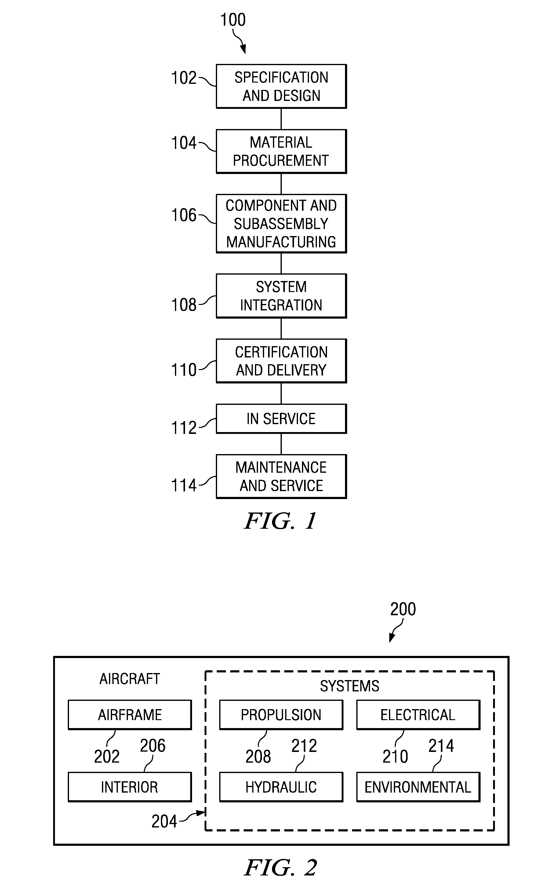
[0030]Referring more particularly to the drawings, embodiments of the disclosure may be described in the context of the aircraft manufacturing and service method 100 as shown in FIG. 1 and aircraft 200 as shown in FIG. 2. Turning first to FIG. 1, a diagram illustrating an aircraft manufacturing and service method is depicted in accordance with an advantageous embodiment. During pre-production, exemplary aircraft manufacturing and service method 100 may include specification and design 102 of aircraft 200 in FIG. 2 and material procurement 104.

[0031]During production, component and subassembly manufacturing 106 and system integration 108 of aircraft 200 in FIG. 2 takes place. Thereafter, aircraft 200 in FIG. 2 may go through certification and delivery 110 in order to be placed in service 112. While in service by a customer, aircraft 200 in FIG. 2 is scheduled for routine maintenance and service 114, which may include modification, reconfiguration, refurbishment, and other maintenance...


PUM

PropertyMeasurementUnit
timeaaaaaaaaaa
speedaaaaaaaaaa
current erroraaaaaaaaaa

Abstract

An apparatus for a drilling operation. In one advantageous embodiment, the drilling operation includes a motor, a rotary sensor, and a controller connected to the rotary sensor. The rotary sensor may be capable of generating a signal in response to rotary movement of the drill motor. The controller may be capable of monitoring a speed of the air motor from the signal generated by the rotary sensor and may be capable of identifying a change from a current layer in a stackup to a new layer in the stackup using the signal.

Description

BACKGROUND INFORMATION[0001]1. Field[0002]The present disclosure relates generally to manufacturing and in particular, to a method and apparatus for drilling holes in objects. Still more particularly, the present disclosure relates to a method and apparatus for adaptively drilling holes in objects with different types of layers.[0003]2. Background[0004]Manufacturing may involve the use of tools and / or labor to create items for use or sale. In aerospace manufacturing, these items may include, for example, without limitation, aircraft, aircraft parts, missiles, rockets, and / or spacecraft. In manufacturing various items, a number of different operations may be performed. These operations may include, for example, without limitation, extrusion, pressing, rolling, piercing, machining, drilling, routing, and curing.[0005]With respect to drilling, a drill may be used to create holes or channels that may be cylindrical in solid materials. A drill may be a tool with a rotating section that m...

Claims


Application Information

Patent Timeline
Patent Type & Authority Patents(United States)
IPC IPC(8): B23B39/08
CPCB23B35/00G05B19/4163B23B2215/04B23B2222/88B23B2226/275Y10T408/173G05B2219/45129G05B2219/49097Y10T408/65Y10T408/165Y10T408/44G05B2219/41363
Inventor MERKLEY, ALAN R.OUTOUS, RONALD W.
Owner THE BOEING CO
Why Eureka
Try Eureka