Impeller, fan apparatus using the same, and method of manufacturing impeller

a technology of fan apparatus and impeller, which is applied in the direction of liquid fuel engine, vessel construction, marine propulsion, etc., can solve the problems of increasing noise levels in the surge range, deteriorating static pressure characteristics, etc., and achieves the effect of improving characteristics, reducing the influence of centrifugal force on blades, and stabl

Active Publication Date: 2012-11-27
NIDEC SERVO CORP
View PDF26 Cites 5 Cited by
  • Summary
  • Abstract
  • Description
  • Claims
  • Application Information

AI Technical Summary

Benefits of technology

[0012]Preferred embodiments of the present invention provide an impeller capable of providing stable air currents, with improved characteristics and an ability to reduce the influence of a centrifugal force on blades. Preferred embodiments of the present invention also provide a fan apparatus including the impeller and a method of manufacturing the impeller.
[0014]In the impeller according to this preferred embodiment of the present invention, the plurality of blades extend radially outward from the outside surface of the support portion of the impeller, and in each of the blades, the point of intersection of the leading edge of the blade with the blade end of the blade is positioned forward relative to the point of intersection of the leading edge with the outside surface of the support portion with respect to the rotation direction. Therefore, a centrifugal force produced on entire portions of each blade during rotation of the impeller produces a large moment at a base of the blade. In the impeller according to this preferred embodiment, the substantially annular joining member extends in the circumferential direction about the central axis to join the blades to one another. This joining member contributes to: 1) reducing the moment produced at the base of each blade due to the influence of the centrifugal force, and 2) preventing each blade from being deformed and the radially outer end of each blade from being displaced radially outward. This allows the impeller to blow air stably while reducing the influence of the centrifugal force on its blades. For example, even when the impeller is caused to rotate at a high speed, the moment produced at the base of each blade due to the influence of the centrifugal force can be reduced to ensure stable air blowing.
[0015]Moreover, since the substantially annular joining member is arranged radially inward of the radially outer end of each blade, it is possible to allocate different roles to radially inward and outward portions of each blade as divided by the joining member. For the region radially inward of the joining member, the joining member assumes the role of a venturi, and there is accordingly no gap between this virtual venturi (i.e., an inner surface of the joining member) and the portion of each blade which is positioned radially inward of the joining member. Accordingly, this contributes to preventing occurrence of backward airflows in the region radially inward of the joining member which results in most of the backward airflows passing through the region radially outward of the joining member. This allows the portion of each blade which is positioned radially outward of the joining member to primarily serve to prevent the occurrence of the backward airflows when the impeller is caused to operate in a surge range. This leads to an improvement in characteristics of the impeller to enable stable air blowing.

Problems solved by technology

This phenomenon manifests itself most strikingly in a surge range which leads to a deterioration in the static pressure characteristic and increased noise levels in the surge range.
This problem manifests itself noticeably in cases where the joining member is provided at the radially outer ends of the blades.

Method used


Image

  • Impeller, fan apparatus using the same, and method of manufacturing impeller
  • Impeller, fan apparatus using the same, and method of manufacturing impeller
  • Impeller, fan apparatus using the same, and method of manufacturing impeller

Examples


Embodiment Construction

1. First Preferred Embodiment

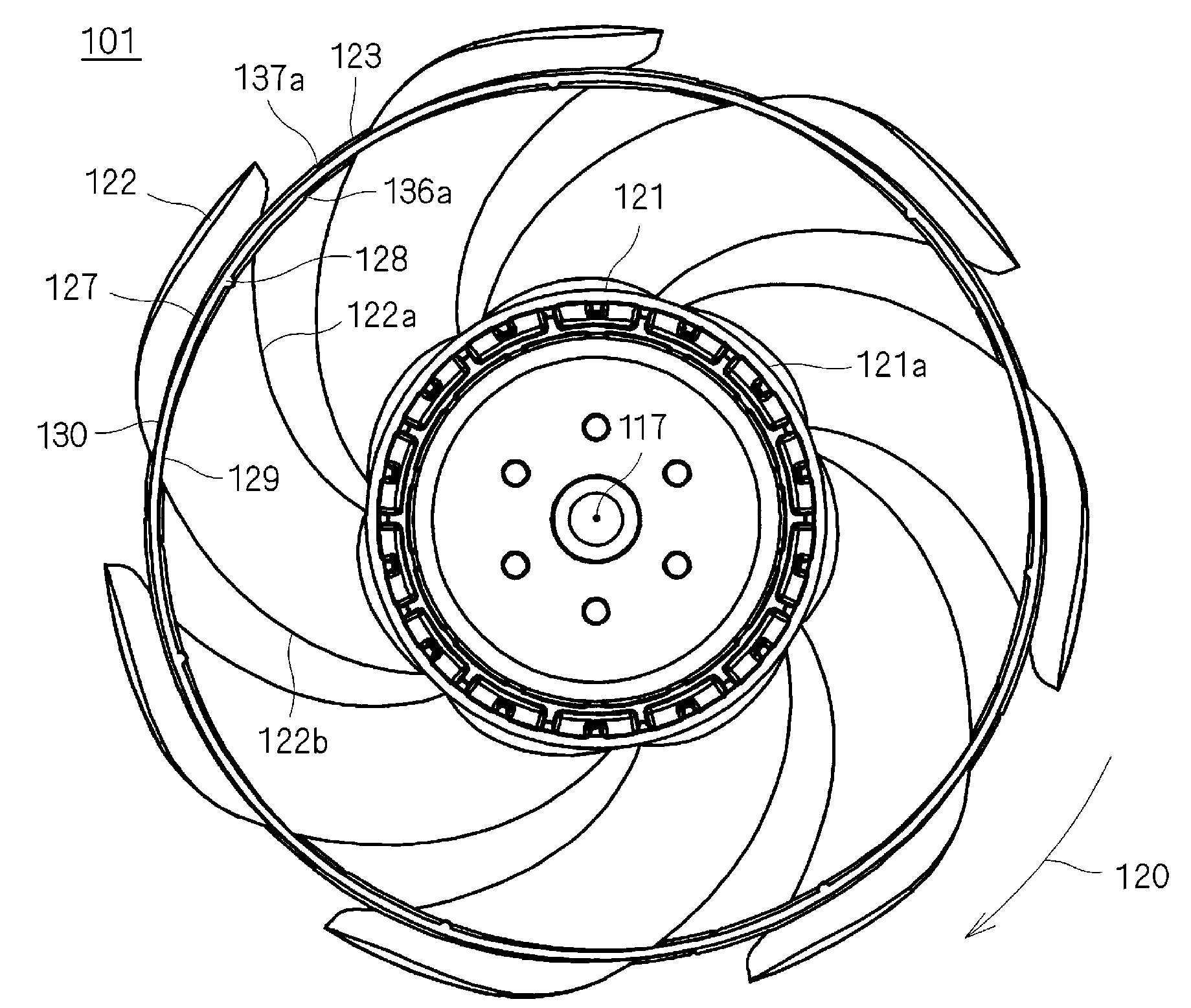
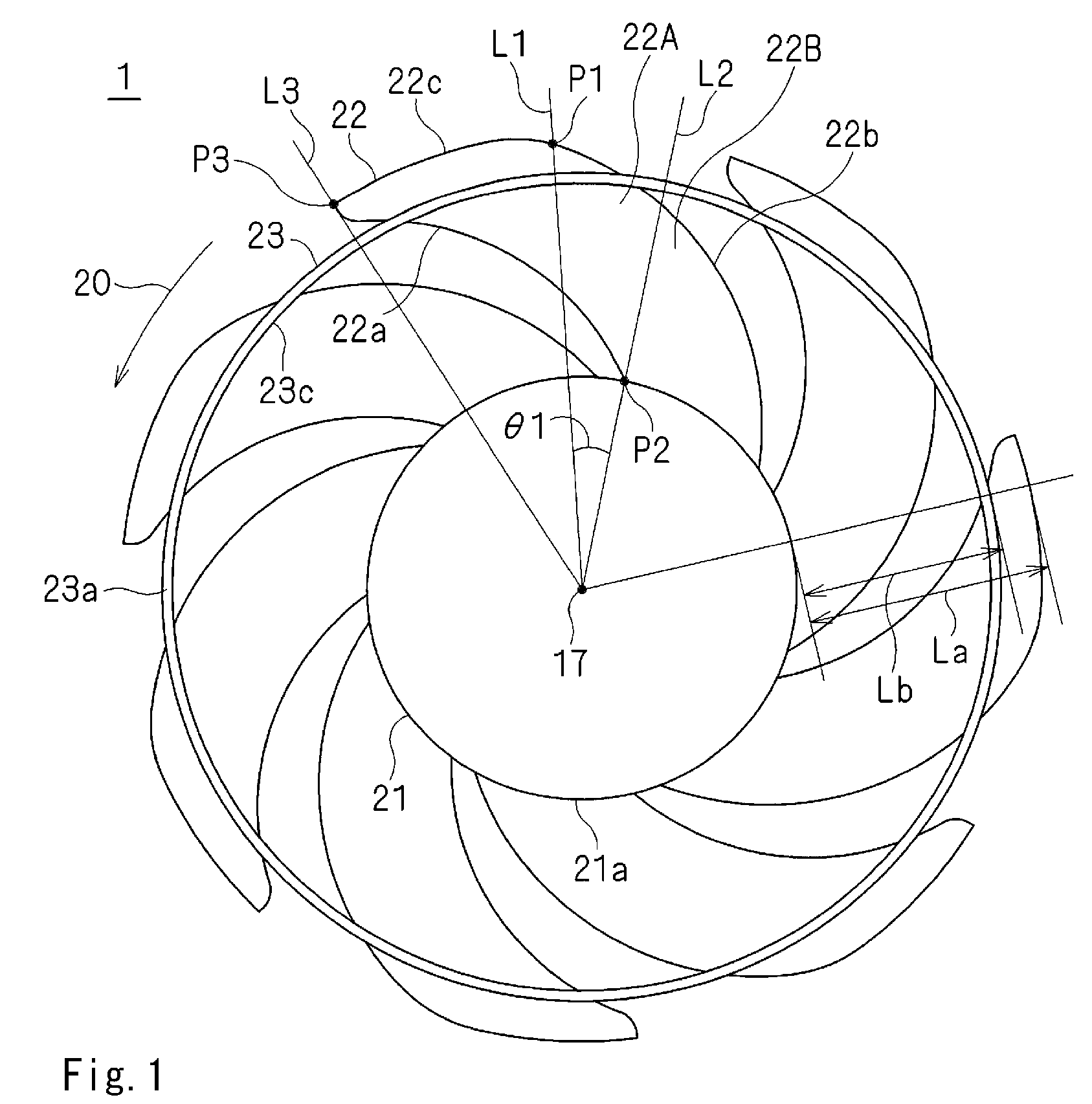
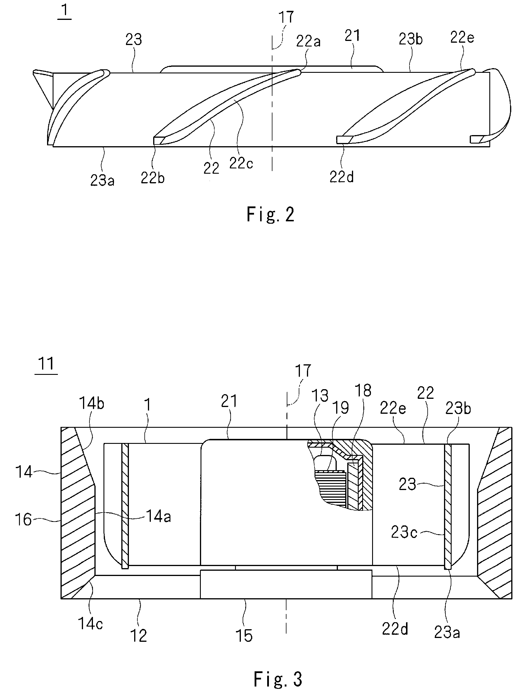
[0033]FIG. 1 is a plan view of an impeller 1 according to a first preferred embodiment of the present invention, as viewed from an inlet side along a central axis 17. FIG. 2 is a side view of the impeller 1 as illustrated in FIG. 1. FIG. 3 is a cross-sectional view of a fan apparatus 11 using the impeller 1 as illustrated in FIG. 1.

[0034]Referring to FIG. 3, the fan apparatus 11 using the impeller 1 according to the present preferred embodiment includes the impeller 1, a plurality of stationary vanes 12, a motor 13, an outer frame member 14, and a support member 15. The stationary vanes 12, the outer frame member 14, and the support member 15 define a housing 16 of the fan apparatus 11. Note that in the present preferred embodiment, the stationary vanes 12 and the support member 15 are, for example, provided on an outlet side (i.e., a lower side in FIG. 3) along the central axis 17 of the impeller 1, but could be provided on the inlet side if so desired....


PUM

PropertyMeasurementUnit
angle θ1aaaaaaaaaa
angle θ1aaaaaaaaaa
angle θ1aaaaaaaaaa

Abstract

An impeller, a fan apparatus, and a method of manufacturing the impeller are provided. The impeller includes a support portion, a plurality of rotor blades, and a joining member. The joining member is a substantially annular member provided to strengthen the rotor blades against influence of a centrifugal force, and extends in a circumferential direction along a circle centered on a central axis so as to join the rotor blades to one another. In each of the rotor blades, a point of intersection of a leading edge of the rotor blade with a radially outer end of the rotor blade is positioned forward, with respect to a rotation direction, relative to a point of intersection of the leading edge with an outside surface of the support portion. The joining member is positioned radially inwards of the radially outer end of each of the rotor blades.

Description

BACKGROUND OF THE INVENTION[0001]1. Field of the Invention[0002]The present invention relates to an impeller having blades with a swept-forward shape and arranged to produce an airflow along a central axis thereof, about which the impeller rotates, a fan apparatus using this impeller, and a method of manufacturing the impeller.[0003]2. Description of the Related Art[0004]Electronic devices such as personal computers or servers are often provided with a cooling fan to cool electronic components within a case thereof. There is a demand for an improvement in the performance of the cooling fan with increasing density of the electronic components within the case. In general, the cooling fans can be divided into two types: exhaust fans designed to expel hot air within the case from the case; and blower fans designed to send cooling air directly to the heated electronic components. In the blower fans, the direction of the airflow, i.e., the direction in which the air is sent, is important....

Claims


Application Information

Patent Timeline
Patent Type & Authority Patents(United States)
IPC IPC(8): F04D29/38
CPCF04D29/325F04D29/326F04D29/38F04D29/668
Inventor HIGO, ASAHIHIOKI, TETSUYATANNO, TAROITO, MITSURUSEKIGUCHI, OSAMUYOO, SEUNG-SIN
Owner NIDEC SERVO CORP
Why Eureka
Try Eureka