Tissue puncture assemblies and methods for puncturing tissue

a tissue and assembly technology, applied in the field of tissue puncture assemblies and methods, can solve the problems of inadvertent puncture of heart structures, inadvertent puncture of transseptal punctures, and numerous potential complications of transseptal punctures, and achieve the effect of preventing inadvertent puncture of other tissues or structures

Active Publication Date: 2012-11-27
ARUZE GAMING AMERICA +1
View PDF40 Cites 116 Cited by
  • Summary
  • Abstract
  • Description
  • Claims
  • Application Information

AI Technical Summary

Benefits of technology

[0030]An advantage of the present invention is that it provides a tissue puncture assembly capable of puncturing a tissue at an oblique angle.
[0031]Another advantage of the present invention is that it provides a tissue puncture assembly having an anchor for maintaining access to the puncture site.
[0032]Still another advantage of the present invention is that it provides a tissue puncture assembly capable of automatically adopting an atraumatic shape after puncturing a tissue to prevent inadvertent puncture of other tissues or structures.

Problems solved by technology

Nevertheless, transseptal puncture has numerous potential complications.
For instance, advancing the needle beyond the interatrial septum may result in inadvertent puncture of heart structures such as the left atrial free wall.
Moreover, improperly puncturing a site other than the fossa ovalis—a structure notoriously difficult to locate—may lead to certain surgical complications.
Additionally, reliably verifying that puncture was successful may be complicated by a lack of left atrial access post-puncture.
Many current transseptal needle devices and assemblies do not address these concerns.
For instance, some transseptal needle devices feature a needle which punctures tissue in a substantially straight orientation and cannot be manipulated to puncture tissue at an angle.

Method used


Image

  • Tissue puncture assemblies and methods for puncturing tissue
  • Tissue puncture assemblies and methods for puncturing tissue
  • Tissue puncture assemblies and methods for puncturing tissue

Examples


Embodiment Construction

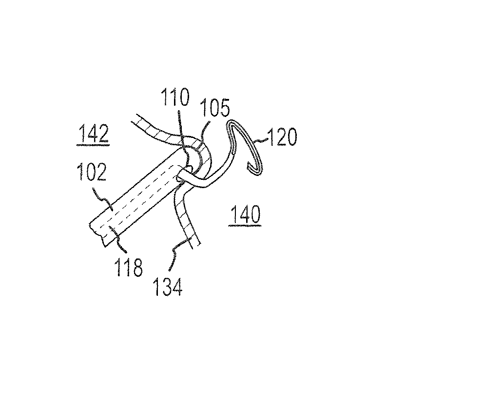
[0047]Disclosed herein is a tissue puncture assembly capable of puncturing a tissue at an oblique angle. The invention will be described in connection with puncturing the interatrial septum and the pericardial sac. It is contemplated, however, that the described device and methods may be utilized to puncture any number of tissues within the body, as would be appreciated by one of ordinary skill in the art.

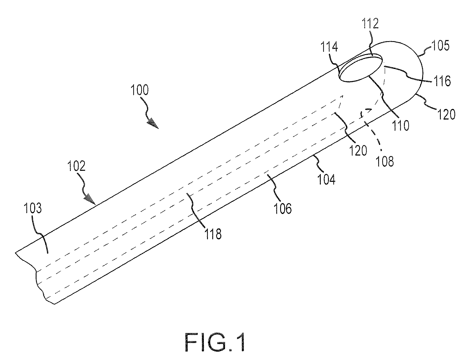
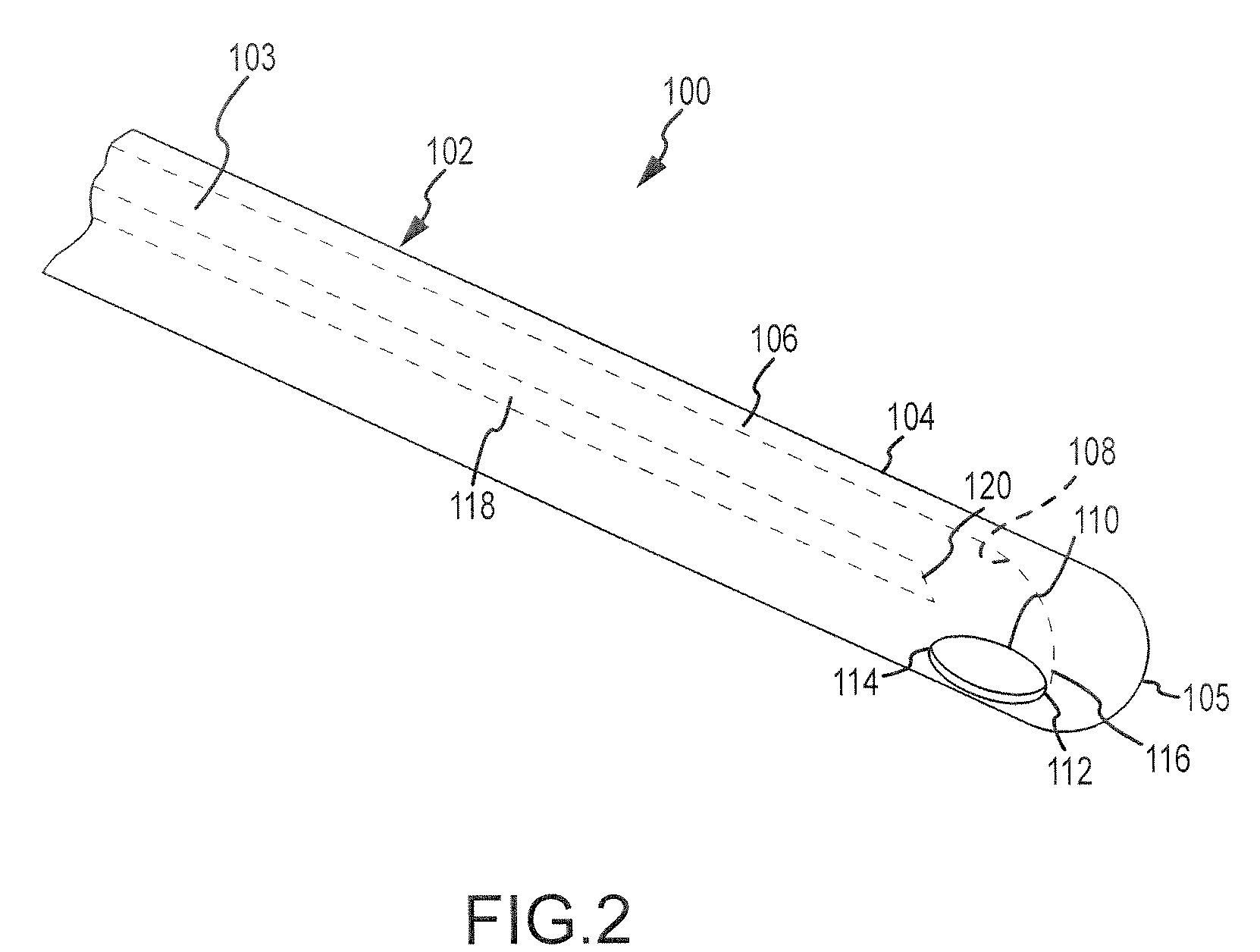
[0048]Referring now to FIGS. 1-2, a tissue puncture assembly 100 includes an elongate tubular member 102 having a lumen 103 (shown in phantom) extending therethrough and a distal portion 104. The distal portion 104 includes a side wall 106, and a side port opening 110 extends through the side wall 106. The side port opening 110 has a distal edge 112 and a proximal edge 114. A guiding surface 108 is disposed within the lumen 103 of the elongate tubular member 102. The guiding surface 108 has a distal end 116 which extends adjacent to the distal edge 112 of the side port opening 110....


PUM


Abstract

A tissue puncture assembly includes an elongate tubular member having a lumen, a distal portion having a side wall, a side port opening extending through the side wall and, and a guiding surface having a distal end that extends adjacent to a distal edge of the side port opening. The tissue puncture assembly further includes a flexible puncture member insertable through the lumen of the elongate tubular member. The flexible puncture member deflects upon contacting the guiding surface to exit the elongate tubular member through the side port in a lateral direction relative to a longitudinal direction of the elongate tubular member. The tissue puncture member is capable of puncturing tissue at an oblique angle. The tissue puncture member may further adopt a pre-formed shape at its distal end to prevent inadvertent puncture of tissue and to maintain access to the puncture site. The transseptal puncture assembly may include various sensors to identify tissue structures and precisely locate the desired puncture site.

Description

BACKGROUND OF THE INVENTION[0001]a. Field of the Invention[0002]The present invention pertains generally to devices and methods for puncturing tissue within the body. More particularly, the invention is directed to devices and methods for puncturing the interatrial septum and / or pericardial sac to facilitate atrial and / or epicardial ablation.[0003]b. Background Art[0004]The traditional method for gaining access to the left atrium is to puncture the interatrial septum at the location of the fossa ovalis. Access to the left atrium is needed for a variety of therapeutic medical procedures, for example left atrial radiofrequency catheter ablation. Nevertheless, transseptal puncture has numerous potential complications. For instance, advancing the needle beyond the interatrial septum may result in inadvertent puncture of heart structures such as the left atrial free wall. Moreover, improperly puncturing a site other than the fossa ovalis—a structure notoriously difficult to locate—may le...

Claims


Application Information

Patent Timeline
Patent Type & Authority Patents(United States)
IPC IPC(8): A61B17/34
CPCA61B17/00234A61B8/12A61B17/320016A61B17/3415A61B18/1492A61B2017/00084A61B2017/00247A61B2018/00392A61B2019/5278A61B2090/3782
Inventor STANGENES, TODD RAYMONDPAUL, SAURAV
Owner ARUZE GAMING AMERICA
Why Eureka
Try Eureka