Three-terminal spin-torque oscillator (STO)

a spin-torque oscillator and three-terminal technology, applied in the field of spin-torque oscillators, can solve the problems of high low-frequency magnetic noise, reduced sensor signal-to-noise ratio (snr) to an undesirable level, and increased magnetoresistance but susceptible to damage,

Active Publication Date: 2012-11-27
WESTERN DIGITAL TECH INC
View PDF23 Cites 52 Cited by
  • Summary
  • Abstract
  • Description
  • Claims
  • Application Information

AI Technical Summary

Benefits of technology

[0011]In one specific application the STO is a magnetic field sensor, such as a current-perpendicular-to-the-plane (CPP) disk drive read head. In this application the STO sensor has a single free ferromagnetic layer that has an in-plane magnetization substantially free to oscillate in the presence of external magnetic fields to be sensed, such as the magnetized “bits” or regions on the disk. The free layer forms part of both a TMR structure with tunnel barrier layer and a first reference layer having a fixed in-plane magnetization, and a GMR structure with a nonmagnetic conductive spacer layer and a second reference layer having a fixed in-plane magnetization. The STO sensor has three electrical contacts or terminals for connection to electrical circuitry. A first terminal is electrically coupled to the first reference layer, a second terminal is electrically coupled to the second reference layer, and a third terminal is electrically coupled to either the conductive spacer layer or the free layer. The electrical circuitry connected to the STO terminals includes an excitation current source and a sense current source. The excitation current is greater that the critical current for the GMR structure and is high enough to provide sufficient current density to cause the magnetization of the free layer to oscillate at a fixed base frequency in the absence of an external magnetic field. The sense current is less than the critical current for the TMR structure. A detector coupled to the sense current detects shifts in the free layer magnetization oscillation frequency from the base frequency in response to the external magnetic fields from the magnetized regions of the disk.

Problems solved by technology

If Is is greater than some critical current (Ic) the spin-torque (ST) effect can produce gyrations or fluctuations of the free layer magnetization, resulting in substantial low-frequency magnetic noise that reduces the sensor's signal-to-noise ratio (SNR) to an undesirable level.
An STO sensor based on a CPP-TMR sensor has a significantly higher magnetoresistance but is susceptible to dielectric breakdown of the tunnel barrier at high current density.

Method used


Image

  • Three-terminal spin-torque oscillator (STO)
  • Three-terminal spin-torque oscillator (STO)
  • Three-terminal spin-torque oscillator (STO)

Examples


Embodiment Construction

Prior Art

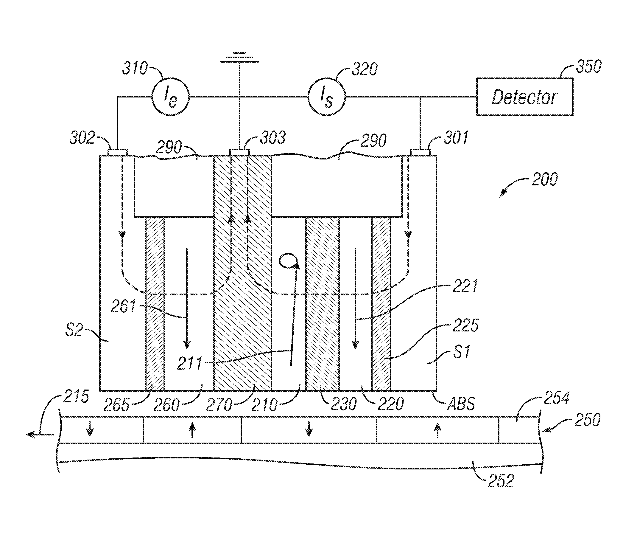
[0021]The three-terminal STO according to the invention has applications other than as a magnetic field sensor, but will be described in detail below as a magnetic recording disk drive read head.

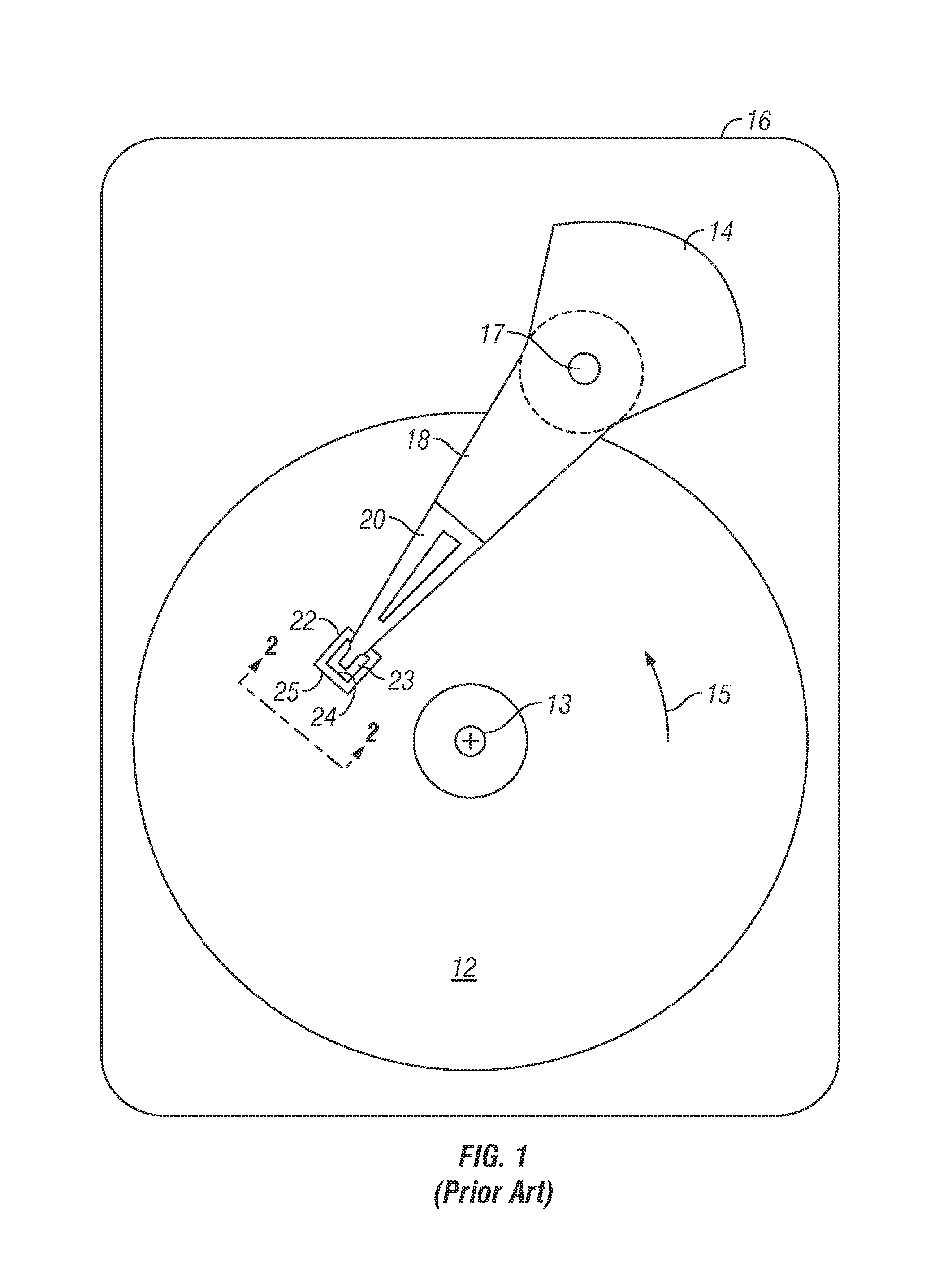
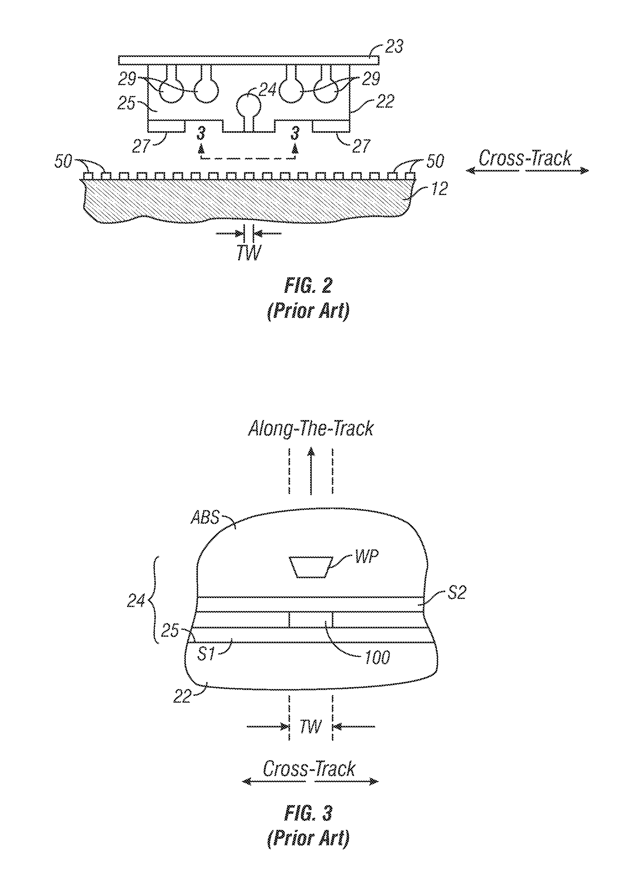
[0022]FIGS. 1-4 illustrate a conventional CPP magnetoresistive (MR) magnetic field sensing sensor and system. FIG. 1 is a block diagram of a conventional magnetic recording hard disk drive. The disk drive includes a magnetic recording disk 12 and a rotary voice coil motor (VCM) actuator 14 supported on a disk drive housing or base 16. The disk 12 has a center of rotation 13 and is rotated in direction 15 by a spindle motor (not shown) mounted to base 16. The actuator 14 pivots about axis 17 and includes a rigid actuator arm 18. A generally flexible suspension 20 includes a flexure element 23 and is attached to the end of arm 18. A head carrier or air-bearing slider 22 is attached to the flexure 23. A magnetic recording read / write head 24 is formed on the trailing surface 25 of slide...


PUM

PropertyMeasurementUnit
thicknessaaaaaaaaaa
frequencyaaaaaaaaaa
frequencyaaaaaaaaaa

Abstract

A spin-torque oscillator (STO) has a single free ferromagnetic layer that forms part of both a giant magnetoresistance (GMR) structure with a nonmagnetic conductive spacer layer and a tunneling magnetoresistance (TMR) structure with a tunnel barrier layer. The STO has three electrical terminals that connect to electrical circuitry that provides a spin-torque excitation current through the conductive spacer layer and a lesser sense current through the tunnel barrier layer. When the STO is used as a magnetic field sensor, the excitation current causes the magnetization of the free layer to oscillate at a fixed base frequency in the absence of an external magnetic field. A detector coupled to the sense current detects shifts in the free layer magnetization oscillation frequency from the base frequency in response to external magnetic fields.

Description

BACKGROUND OF THE INVENTION[0001]1. Field of the Invention[0002]The invention relates generally to a spin-torque oscillator (STO), and more particularly to a magnetic field sensor and sensing system that uses a STO sensor.[0003]2. Background of the Invention[0004]One type of conventional magnetoresistive (MR) sensor used as the read head in magnetic recording disk drives is a “spin-valve” sensor based on the giant magnetoresistance (GMR) effect. A GMR spin-valve sensor has a stack of layers that includes two ferromagnetic layers separated by a nonmagnetic electrically conductive spacer layer, which is typically copper (Cu). One ferromagnetic layer adjacent the spacer layer has its magnetization direction fixed, such as by being pinned by exchange coupling with an adjacent antiferromagnetic layer, and is referred to as the reference layer. The other ferromagnetic layer adjacent the spacer layer has its magnetization direction free to rotate in the presence of an external magnetic fie...

Claims


Application Information

Patent Timeline
Patent Type & Authority Patents(United States)
IPC IPC(8): G11B5/127G11B5/187
CPCG01R33/098G01R33/1284G11B5/3903H01L43/08H01F10/3286H01F10/3254H01F10/329H01F10/1936G11B2005/0005H10N50/10
Inventor BRAGANCA, PATRICK MESQUITAGURNEY, BRUCE ALVINKATINE, JORDAN ASHER
Owner WESTERN DIGITAL TECH INC
Why Eureka
Try Eureka