
Method and system for surface sampling

a surface sampling and surface technology, applied in the field of surface sampling, can solve the problems of limiting the throughput of the method, limiting the sample type and the physical size and shape of the sample that can be analyzed, and significant challenges to the desorption and ionization of analytes from the surface, so as to improve the depth of sample interrogation and the range of analytes, and improve the quality of sample characterization. , the effect of reducing or disrupting

Active Publication Date: 2012-12-04
PROSOLIA +1
View PDF12 Cites 15 Cited by
  • Summary
  • Abstract
  • Description
  • Claims
  • Application Information

AI Technical Summary

Benefits of technology

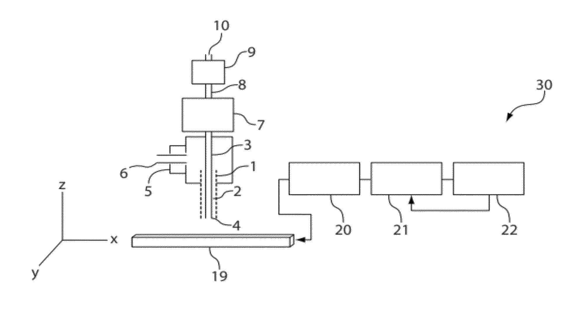
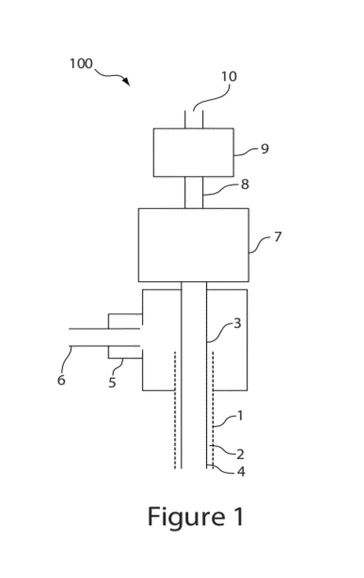
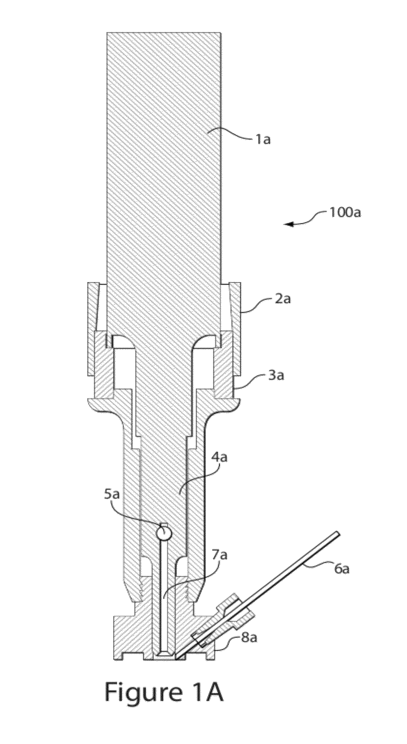
[0013]Analyte desorption from the surface is accomplished via dissolution or release of the sample by the irrigating fluid acting in concert with the applied ultrasonic energy. As such, the ultrasonic energy enhances and accelerates desorption, and extends both the depth of sample interrogation, and the range of analytes that will be desorbed into the irrigation fluid, by one or more physical mechanisms that effectively disrupt the binding or structure holding the analyte in or at material of the probed surface. Mechanisms causing the surface to release analyte—adsorbed atoms or molecules, whole cells, or intracellular or endocellular components and other material—may include local shock—induced stress, cavitation or the like, or may include mechanical mechanisms such as vibratory shear imposed by the vibrating fluid-to-matrix contact at the site of analysis, as well physico-chemical effects lowering or disrupting barriers such as surface energy, relative dilution, energy of solvation, or the enhancement of diffusive or rheological migration of analyte, including adhered, bound or poorly-mobile analyte from the target matrix material into the fluid.

Problems solved by technology

The high vacuum environment of these processes poses inherent limitations to the type of sample and to the physical size and shape of sample that can be analyzed.
These limitations often make it necessary to perform several sample preparation steps prior to analysis, thus also limiting the throughput of the method.
However, despite these recent advances in surface sampling mass spectrometry, significant challenges still remain with respect to desorption and ionization of analytes from surfaces since the analyte and the substrate may each present a wide range of different characteristics and chemical matrices.
While the latter is advantageous, the former poses limitations since solvents or energetic processes are generally used to promote desorption.
Therefore, the development of new methods having the capacity to efficiently disrupt the interaction of analytes bound to or within a target surface, and to extract desired analytes for analysis in an instrument non-proximate to the device, is a highly desirable capability that is inadequately achieved by the current methods.
Another limitation of current methodologies is the requirement for precise alignment of the desorption / ionization source with the target object and with the sample-receiving inlet of the analysis instrument.
While that methodology constituted an advance, it remained restricted in its ability to be oriented properly to a target surface, since the spray and inlet are fixed within an enclosure.
The prerequisite for forming a stable liquid junction between the solvent and the sample surface poses limitations on analysis.
While large particles may be removed from the surface as “chunks”, configurations of the instrument may largely suppress such unsuitable material in the analysis stream because such chunks may exhibit sufficient momentum that they are not swept into the sampling capillary, thus not reaching the ionization assembly if one is present; or such material may be separated after passing through the capillary following a downstream ionization stage by their different trajectories ahead of the mass spectrometer or other analysis instrument.

Method used


Image

  • Method and system for surface sampling
  • Method and system for surface sampling
  • Method and system for surface sampling

Examples


example 1

[0050]Rhodamine dye (molecular weight 443) was deposited on an inert Teflon surface and was sampled by the probe head using an irrigant / solvent desorption solvent comprised of a 50:49.9:1 mixture of acetonitrile, water and formic acid, using a 40 kHz drive signal at 50 W power. The aspirated flow was coupled as the input to a Thermo Scientific LTQ linear ion trap mass spectrometer. FIG. 7 shows the selected ion current at m / z 443 and the normalized intensities.

example 2

Parathyroid hormone (PTH), of molecular weight (MW) 4117 was deposited onto a titanium surface and was then sampled and analyzed as in Example 1. The protonated ions were detected as shown in the spectrum of FIG. 8.

example 3

[0051]After dosing with clozapine at 50 mg / kg, a rat was sacrificed and the probe was used to gather a sample from an intact kidney. FIG. 9 shows the MS / MS mass spectrum of m / z 327±1.5 corresponding to the protonated ion of clozapine (MW: 326), sampled as in Examples 1 and 2. The inset shows the structure and the site of cleavage of the ion resulting in a neutral loss of 57 Daltons and the resultant ion at m / z 270.


PUM

PropertyMeasurementUnit
frequencyaaaaaaaaaa
frequenciesaaaaaaaaaa

Abstract

A system and sampling probe adaptable to an ultrasonic surgical instrument applies irrigation fluid and ultrasonic or vibrational energy to a target, and aspirates material desorbed from the target into a pick-up conduit. A suction source at the distal end of the conduit may aspirate the material released from the target with the irrigation fluid, thus efficiently sampling a broad range of materials from an arbitrary target to produce an analyzable effluent analyte stream which may be ionized and provided to the inlet of an ion-type analysis instrument, or may be fed directly to an instrument such as a flow cytometer, IR or fluorescence spectrophotometer, or other analyzer. Carrier gas may be provided to more effectively transport the desorbed material, and the probe may be incorporated into a robotic device to automatically carry out surface imaging or to effect sampling in hazardous environments.

Description

RELATED APPLICATIONS[0001]The present application claims the benefit of U.S. provisional application Ser. No. 61 / 165,635 filed in the U.S. Patent and Trademark Office Apr. 1, 2009, and is a continuation of and claims the benefit of international application PCT / US10 / 29586 filed Apr. 1, 2010 and published Oct. 7, 2010, each of which is hereby incorporated by reference herein in its entirety.FIELD OF INVENTION[0002]The present invention relates to sampling and detection of material such as atoms, molecules, molecular clusters and intact cells or other material present on and removed from a target object for analysis. The method employs a probe which applies vibrational or ultrasonic energy to the target object to desorb or release analytes from the target, and aspirates the desorbed material forming an analyte effluent for presentation to an analysis instrument, such as a mass spectrometer, flow cytometer, spectrophotometer or other analysis instrument.BACKGROUND OF INVENTION[0003]Sur...

Claims


Application Information

Patent Timeline
Patent Type & Authority Patents(United States)
IPC IPC(8): H01J49/04
CPCG01N35/1095H01J49/0459Y10T29/49826
Inventor WISEMAN, JUSTINAGAR, NATHALIE
Owner PROSOLIA
Learn More