Inter-cell interference co-ordination

a cell interference and interference technology, applied in the field of prediction of interference contributions, can solve the problems of reducing transmission power, unable to capture bursty packet data transmissions, and measured interference delays, so as to improve user experience, improve transmission efficiency, and improve the accuracy of radio link quality estimation

Active Publication Date: 2012-12-04
TELEFON AB LM ERICSSON (PUBL)
View PDF22 Cites 48 Cited by
  • Summary
  • Abstract
  • Description
  • Claims
  • Application Information

AI Technical Summary

Benefits of technology

[0012]An advantage of the present invention is that it yields predictable interference, which in turn enables more accurate radio link quality estimation. This enables more efficient adaptation of transmission parameters, e.g. channel, power, modulation, channel coding, which yields higher user quality (e.g. bitrates), higher system capacity, and better coverage.
[0013]A further advantage of the present invention is that the interference per channel is predicted. This enables inter-cell interference co-ordination by scheduling on least interfered frequencies improving system capacity and coverage.
[0014]A yet further advantage of the present invention is that the link quality per channel is better estimated since the interference predicted. Frequency selective scheduling is then improved improving user quality and capacity.

Problems solved by technology

Thus, the co-ordination method and protocols are important and specifically the resulting delay.
When the uplink measured inter-cell interference is high, relative grants can be sent to the user equipment reducing the grant relatively the absolute grant from connected cell resulting in decreased transmission power.
Measured interference is delayed and is not able to capture bursty packet data transmissions.
This result in poor interference prediction degrading the performance of the algorithms based on interference measures.

Method used


Image

  • Inter-cell interference co-ordination
  • Inter-cell interference co-ordination
  • Inter-cell interference co-ordination

Examples


Embodiment Construction

[0019]The invention is defined as a method and an arrangement which may be put into practice in the embodiments described below.

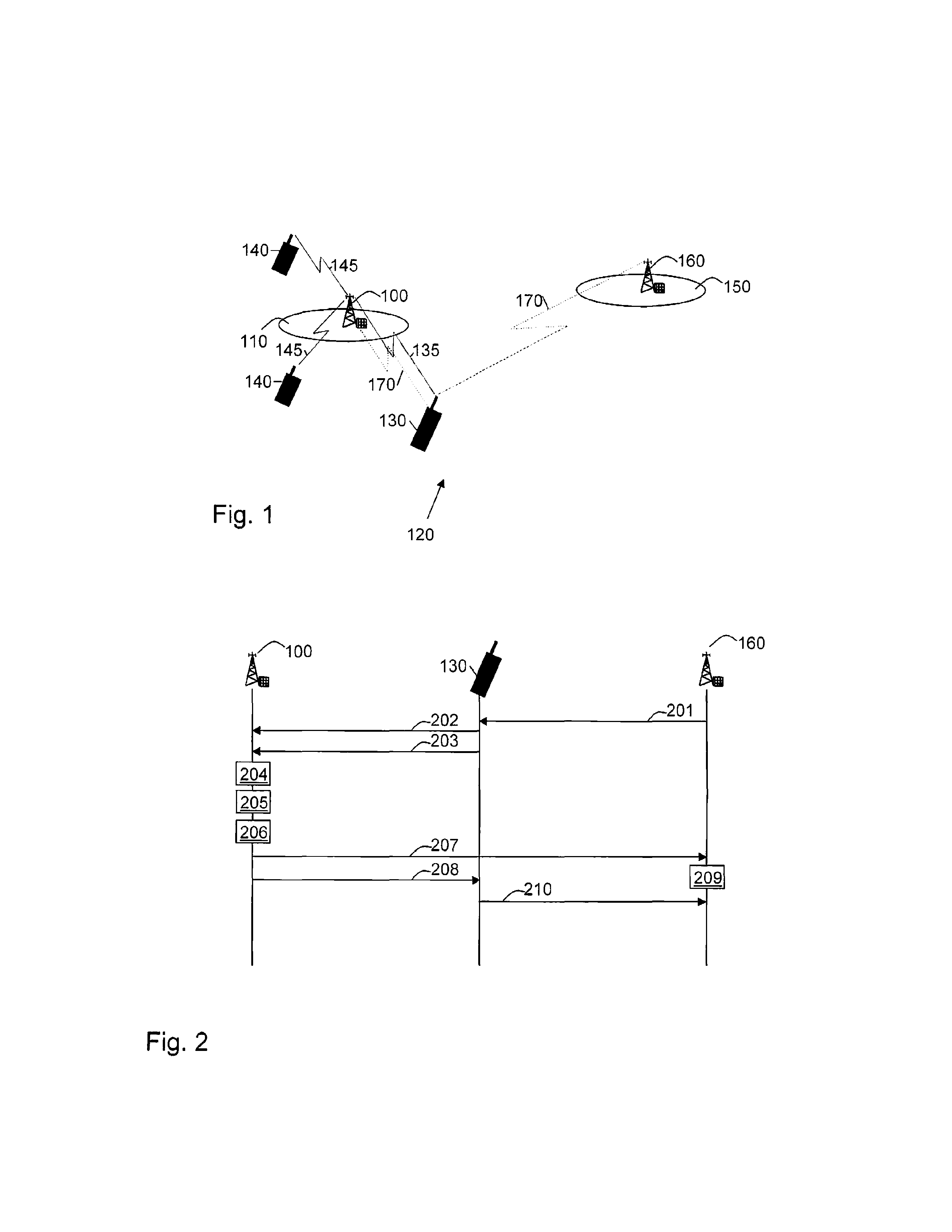
[0020]FIG. 1 depicts a base station 100 serving a cell 110 comprised in a radio access network 120 such as e.g. E-UTRA and Worldwide Interoperability for Microwave Access (WiMAX), UTRA, WLAN WCDMA GSM / GPRS. A first user equipment 130 is connected to the base station 100 which makes it possible for the first user equipment 130 to communicate with the base station 100, using resources 135 such as e.g. resource blocks, frequency bands, time slots), and / or spreading codes. Resource blocks are a frequency channels limited in time. The first user equipment 130 is connected to the cell 110, which cell 110 therefore is referred to as the connected cell 110. The base station 100 may further be connected to second user equipments 140, with which second user equipments 140, the base station 100 can communicate with using resources 145. The first user equipment 130 and...


PUM


Abstract

According to the present invention, a method in a base station is provided for predicting interference contribution, when scheduling an uplink data packet transmission from a first user equipment. The first user equipment is connected to the base station. The first user equipment is in the neighbor of a neighboring cell served by a neighboring base station. The method comprises the steps of: Obtaining signal strength measurements regarding the first user equipment. The signal strength measurements are based on a signal between the first user equipment and the neighboring base station; Receiving a resource scheduling request regarding the first user equipment for the uplink data packet transmission; Scheduling uplink resources for the requested uplink data packet transmission; Determining transmission power to be used for the scheduled uplink resources, and: Estimating an interference prediction contribution based on the determined transmission power and the obtained signal strength.

Description

TECHNICAL FIELD[0001]The present invention relates generally to a method and an arrangement in a base station in a radio access network. In particular it relates to prediction interference contribution.BACKGROUND OF THE INVENTION[0002]Limiting the effects of inter-cell interference is an important factor for the performance of cellular radio communication systems. In Evolved—Universal Terrestrial Radio Access (E-UTRA) it is addressed specifically as Inter-cell interference mitigation. One of the discussed mitigation approaches is to avoid the use of the same frequency at the same time in neighbouring cells by co-ordination. According to E-UTRA, this inter-cell-interference co-ordination / avoidance may be defined for uplink in as: “The common theme of inter-cell-interference co-ordination / avoidance is to apply restrictions or preferences to the uplink scheduling, coordinated between cells. These restrictions can be in the form of restrictions to what time / frequency resources are avail...

Claims


Application Information

Patent Timeline
Patent Type & Authority Patents(United States)
IPC IPC(8): H04J1/16
CPCH04W52/40H04B17/345H04W52/243H04B17/373H04W52/146
Inventor SIMONSSON, ARNEFURUSKAR, ANDERS
Owner TELEFON AB LM ERICSSON (PUBL)
Why Eureka
Try Eureka