Projector apparatus

a projector and apparatus technology, applied in the field of projector apparatus, can solve the problems of increased power consumption, inability to obtain sufficient heat release effect, and inability to obtain desired projection light image, so as to achieve effective cooling, prevent dew condensation, and enhance the energy-saving effect.

Inactive Publication Date: 2010-05-13
SANYO ELECTRIC CO LTD
View PDF1 Cites 30 Cited by
  • Summary
  • Abstract
  • Description
  • Claims
  • Application Information

AI Technical Summary

Benefits of technology

[0013]To solve such technical problems described above, the present invention is intended to provide a projector apparatus which can particularly effectively adapt a cooling device suitable for cooling of a large projector. Therefore, the present invention provides a projector apparatus capable of ensuring stable operation by combining a refrigeration cycle including a refrigerant compressor, and circulating air cooled by a cooling part thereof to an optical chamber to cool an optical device. The present invention involves a novel technique for preventing moisture resulting from evaporation of dew adhered to the cooling part from adversely affecting the optical device upon stoppage of the operation of the refrigeration cycle, and a configuration for effectively cooling the optical device of the projector by storing the optical device in an adiabatically-walled optical chamber.
[0014]The present invention is further intended to effectively cool, in a projector apparatus, a color composition prism, a capacitor lens and the like which are optical elements constituting a color composition optical system for generating projection light, while surely preventing dew condensation thereon after stopping the operation.

Problems solved by technology

Such a projector is associated with a risk of not being able to obtain a desired projection light image due to an adverse effect such as deformation on the optical device by the main body internally heated with the heat generated from the light source or the optical device.
This results in problems such as remarkably increased power consumption in addition to increased noise by the operation of the fans.
Further, the problem of a so-called short cycle of air after heat release is also caused, in which although the external air which receives the heat is discharged to the outside, this discharged external air is sucked again by the fan and supplied to the projector, and a sufficient heat release effect cannot be obtained.
Since the area for disposing the evaporator as the low-temperature part of the refrigeration cycle is not partitioned from the area for disposing the optical device in this system, dew adhered to the evaporator and / or dew fallen from the evaporator evaporate in accordance with a rise of ambient temperature upon stoppage of the operation of the cooling device, and resulting moisture adheres to the optical device, whereby the optical function is deteriorated.
Although the temperatures of the evaporator and the optical device naturally rise upon stoppage of the operation of the cooling device, the optical device including the prism is slow in temperature rise, and if the dew adhered to the evaporator and / or the dew fallen from the evaporator evaporate due to the rise of temperature of the evaporator in a state where the optical device is cooled, resulting moisture adheres to the optical device including the prism, causing the deterioration of the optical function.
Particularly, the adhesion of the moisture to the prism causes deterioration of the composing function as projection light image, resulting in a situation such that a desired image cannot be obtained when the composed projection light image is enlarged and projected onto a screen by a projection lens.
Although the problem of the noise can be solved by the electronic cooling as disclosed in Patent Document 2, this electronic cooling is poor in energy efficiency, and requires a means for releasing heat to external air (heat sink or fan) in the vicinity of a cooling object since a heating part of the electronic cooling is integrally constituted, and a spatial restriction caused thereby leads to a remarkable deterioration of design flexibility.
Further, when the electronic cooling operation is stopped, dew adhered to a cooling part of the electronic cooling evaporates, causing the same problem as in Patent Document 1.
However, the conventional projector apparatus further has the problem of a dew condensation countermeasure to be solved in addition to such a temperature countermeasure.
Although this problem is never caused if a second section having the optical elements of the color composition optical system disposed therein is perfectly sealed and internally perfectly dehumidified in Patent Document 1, even a slight clearance allows penetration of humid external air during the operation, causing dew condensation on the surface of the optical elements of the color composition optical system after stopping the operation.
However, the temperature of the cooler immediately starts rising upon stoppage of the operation due to its high heat exchange efficiency, while the rise of temperature is delayed in the optical elements of the color composition optical system since a color composition prism and a condenser lens particularly have large heat capacities.
However, since the part in which each optical element is disposed is a structurally little part, the cleaning operation is not easy, and even if the cleaning operation is performed, the optical elements or wirings may be damaged.

Method used


Image

  • Projector apparatus
  • Projector apparatus
  • Projector apparatus

Examples


embodiment 1

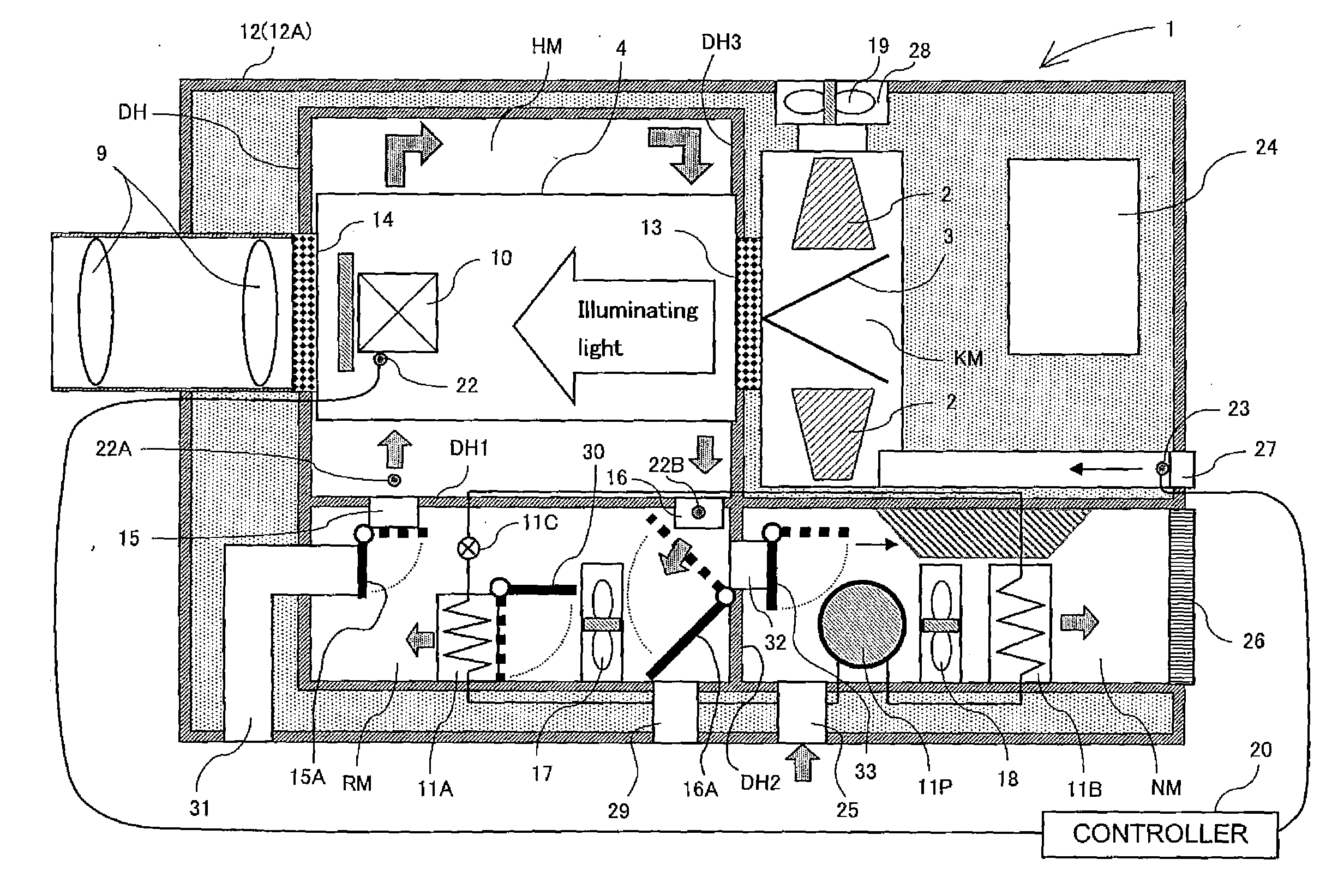
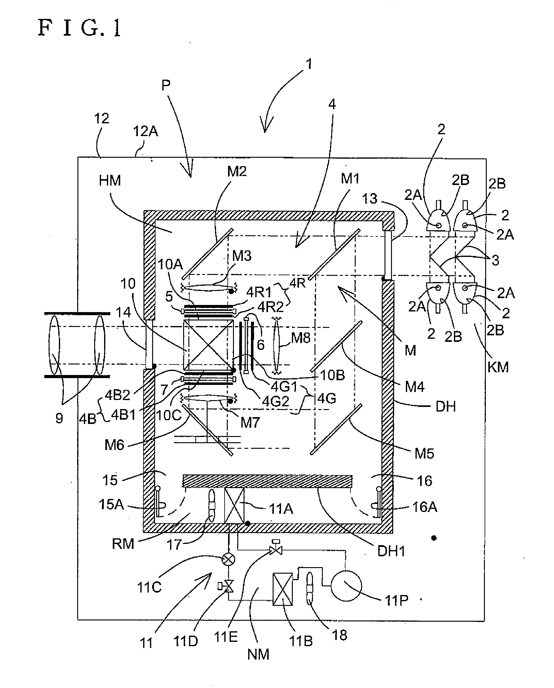
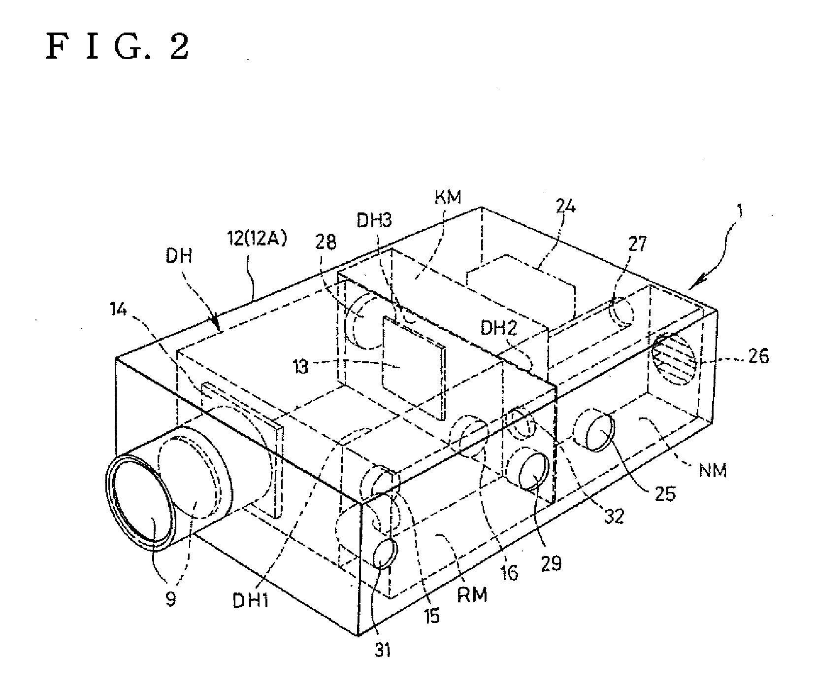
[0131]FIG. 1 is a view schematically showing a functional configuration of a projector apparatus according to the present invention; FIG. 2 is a perspective view of one form of layout structure of each chamber in a box unit 12 according to the present invention; FIG. 3 is a transverse plan view of the one form of layout structure of each chamber in the box unit 12 according to the present invention; FIG. 4 is a structural view of a cooling unit according to the present invention; FIG. 5 is a control block diagram according to the present invention; FIG. 6 is a control functional chart for an internal air circulation mode and an external air (ambient air) introduction mode by the cooling unit; FIG. 7 is a functional chart for after-treatment operation (drying operation) after cooling operation; FIG. 8 is a relationship diagram between external air temperature and optical device part temperature; FIG. 9 is a view showing the state of each damper mechanism in the external air (ambient ...

embodiment 2

[0166]Embodiment 2 is differed from Embodiment 1 in the structure for introducing external air (ambient air) into the optical chamber HM. In Embodiment 2, in order to directly introduce the external air (ambient air) into the optical chamber HM without passing through the cooling chamber RM, an external air inlet port 40 and an external air outlet port 41 are formed in the adiabatic wall DH opposite to the cooling chamber RM of the adiabatic walls of the optical chamber HM. Therefore, the vent port 32 for mutually connecting the cooling chamber RM and the radiation chamber NM is not present on the heat insulating partitioning wall between both the chambers, and the damper mechanism 33 is thus unneeded. The damper mechanism 30 is also unneeded.

[0167]In FIGS. 18 and 19 having the same form of layout structure of each chamber as FIG. 3, a function part having the same form as in the configuration of Embodiment 1 is shown by the same reference number. FIG. 18 shows the state of each dam...

embodiment 3

[0170]In Embodiment 1 and Embodiment 2, the optical chamber HM is composed of a single cooling space capable of housing all of the prism 10, and the liquid crystal panels and polarization plates disposed respectively in opposition to three faces (incident surface of image light of red R, incident surface of image light of green G, and incident surface of image light of blue B) of the prism 10, so that all of the prism 10, the liquid crystal panels and the polarization plates are cooled by allowing the cold air introduced through the cold air inlet port 15 to flow into this cooling space (optical chamber HM).

[0171]Embodiment 3 adopts a distributed cooling system of the optical device 4, differed from this cooling system of the optical device 4 within the single cooling space. In this distributed cooling system, as shown in FIG. 22, three branched cold air passages are constituted to branch the cold air introduced through the cold air inlet port 15, and each space for housing one face...


PUM


Abstract

The present invention provides a projector apparatus capable of ensuring stable operation, which is configured to efficiently cool an optical device by circulating air cooled by a cooling part of a refrigeration unit, and further to prevent moisture resulting from evaporation of dew adhered to the cooling part from adversely affecting the optical device when stopping the operation of the refrigeration unit. The optical chamber and the cooling chamber are enclosed respectively by adiabatic walls, the cooling chamber and the optical chamber are connected to each other through a cold air inlet port and a cold air outlet port, and the cold air inlet port and the cold air outlet port are provided with opening and closing mechanisms. In a cooling operation mode, the optical device is cooled with cold air by opening the opening and closing mechanisms, and upon stoppage of the cooling operation, the opening and closing mechanisms are closed to prevent the inflow of the moisture in the cooling chamber to the optical chamber.

Description

BACKGROUND OF THE INVENTION[0001]1. Field of the Invention[0002]The present invention relates to a projector apparatus configured to process a light emitted from a light source by an optical device and project the processed light as a projection light image onto a screen through a projection lens.[0003]2. Description of the Related Art[0004]Conventionally, this type of projectors, for example, a liquid crystal projector comprises a light source, an optical device including a deflection plate, a liquid crystal panel and a prism, a projection lens and the like, which are mounted within a main body. The liquid crystal panel generally includes, as light bulbs, three liquid crystal panels corresponding to light's three primary colors for processing (modulating) each color light according to image information. The light emitted from the light source is separated into each color light, which is then processed (modulated) according to image information by each liquid crystal panel through t...

Claims


Application Information

Patent Timeline
Patent Type & Authority Applications(United States)
IPC IPC(8): G03B21/16
CPCG03B21/16H04N9/3167H04N9/3144
Inventor ITSUKI, HIROYUKIKUROSAWA, YOSHIAKI
Owner SANYO ELECTRIC CO LTD
Why Eureka
Try Eureka