Optical fiber coupler array

a coupler array and optical fiber technology, applied in the field ofcouplers, can solve the problems of increasing the insertion loss, reducing the coupling coefficient at each interface, and significant challenges in interfacing optical waveguide devices, and achieve the effects of low loss, high coupling coefficient, and maximizing coupling coefficien

Active Publication Date: 2012-12-04
CHIRAL PHOTONICS
View PDF8 Cites 34 Cited by
  • Summary
  • Abstract
  • Description
  • Claims
  • Application Information

AI Technical Summary

Benefits of technology

[0013]The present invention is directed to an optical fiber coupler array capable of providing multiple low loss, high coupling coefficient interfaces between a predetermined number of low numerical aperture optical fibers, and an optical waveguide device with at least a corresponding number of waveguide interfaces. The novel coupler array includes a plurality of coupler inner cores and a plurality of corresponding coupler outer cores, within a medium surrounding each plural outer core, and also includes a first end for interfacing with plural optical fibers and a second end for interfacing with a plurality of waveguide interfaces of an optical waveguide device. The sizes of the inner and outer cores are gradually reduced from the first end to the second end in accordance with at least one predetermined reduction profile. Various parameters, such as refractive indices and sizes of the inner and outer cores and the medium (as well as the reduction profile), are preferably selected, in accordance with the present invention, to produce a plurality of low numerical aperture waveguides at the first end, and to produce a plurality of high numerical aperture waveguides at the second end, while advantageously minimizing insertion loss and maximizing the coupling coefficient at each end. Advantageously, the inventive coupler array may be fabricated as an array of individually drawn couplers from multiple parallel fused performs (arranged in a row, or in another geometric cross section).

Problems solved by technology

However, there are significant challenges in interfacing optical waveguide devices, including chiral optical fiber devices, with conventional low index contrast optical fibers.
Failure to properly address these obstacles results in increased insertion losses and a decreased coupling coefficient at each interface.
Nevertheless, a number of challenges still remain.
With the proliferation of optical devices with multiple waveguide interfaces (e.g., waveguide arrays), establishing low loss high-accuracy connections to arrays of high numerical aperture waveguides often provide problematic, especially because the spacing between the waveguides was very small making coupling thereto all the more difficult.

Method used


Image

  • Optical fiber coupler array
  • Optical fiber coupler array
  • Optical fiber coupler array

Examples


first embodiment

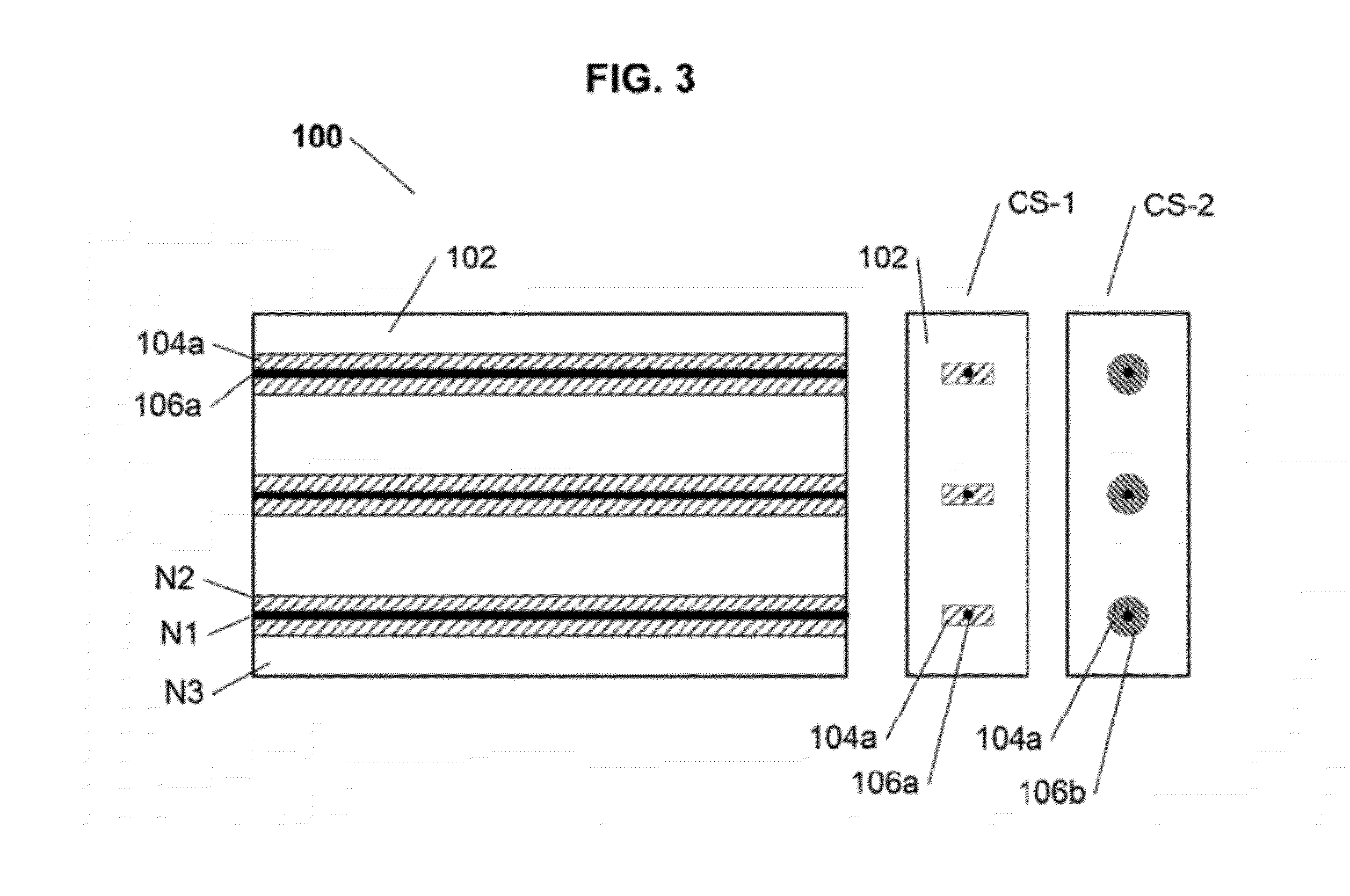
[0024]Referring now to FIG. 3, an optical fiber coupler array perform that may be utilized to fabricate the inventive optical fiber coupler array 10a, 10b of FIGS. 1A and 1B is shown, with plural inner cores 106a and outer cores 104a embedded in parallel within a single perform medium 102 (made from glass or polymer for example). By way of example, if the resulting optical coupler array is intended to be polarization maintaining, then, as is shown in cross section view CS-1, the outer cores 104a may have 180 degree cross-sectional symmetry (e.g. a rectangle cross-section). Otherwise as shown in view CS-2, the outer cores 104a may be conventional.

second embodiment

[0025]Referring now to FIGS. 4A and 4B, an exemplary optical fiber coupler array perform 100 that may be utilized to fabricate the inventive optical fiber coupler array 50 of FIG. 2 is shown. FIG. 4A shows a stage of initial preparation thereof, wherein a set of performs 150a-150d, each comprising an inner core 154a, and an outer core 156a surrounded by a medium 152a, are connected to one another in parallel to each (for example by being fused together). FIG. 4B, then shows a ready for use perform 200 comprising the four performs 150a-150d in a square cross-section configuration, which by way of further example is shown, in view CS-3, as having a square cross-section with polarization maintaining outer cores 156a. As noted above, this exemplary perform 200 may be used to fabricate an embodiment of the inventive coupler array which comprises a plurality of individually drawn high numerical aperture waveguide couplers (such as coupler array 50 of FIG. 2).


PUM


Abstract

An optical fiber coupler array capable of providing multiple low loss, high coupling coefficient interfaces between a predetermined number of low numerical aperture optical fibers and an optical waveguide device with at least a corresponding number of waveguide interfaces. The novel coupler array includes a plurality of coupler inner cores and a plurality of corresponding coupler outer cores, within a medium surrounding each plural outer core, and also includes a first end for interfacing with plural optical fibers and a second end for interfacing with a plurality of waveguide interfaces of an optical waveguide device. The sizes of the inner and outer cores are gradually reduced from the first end to the second end in accordance with at least one predetermined reduction profile. Various parameters, such as refractive indices and sizes of the inner and outer cores and the medium (as well as the reduction profile) are selected to produce a plurality of low numerical aperture waveguides at the first end, and a plurality of high numerical aperture waveguides at the second end, while advantageously minimizing insertion loss and maximizing the coupling coefficient at each end. Advantageously, the novel coupler array may be fabricated as an array of individually drawn couplers from multiple parallel fused performs (arranged in a row, or in another geometric cross section). Alternately, the novel coupler array may be fabricated from a single perform (glass or polymer) embedded with a plurality of parallel inner and outer core sets.

Description

CROSS REFERENCE TO RELATED APPLICATIONS[0001]The present patent application claims priority from the commonly assigned co-pending U.S. provisional patent application Ser. No. 61 / 080,684, entitled “Optical Fiber Coupler Array”, filed Jul. 14, 2008.FIELD OF THE INVENTION[0002]The present invention relates generally to couplers, and more particularly to an optical fiber device comprising an array of multiple optical fiber couplers capable of providing multiple low loss, high coupling coefficient interfaces between a predetermined number of low numerical aperture optical fibers and an optical waveguide device with at least a corresponding number of waveguide interfaces.BACKGROUND OF THE INVENTION[0003]Optical waveguide devices are indispensable in various high technology industrial applications, and especially in telecommunications. In recent years, these devices, including planar waveguides, and two or three dimensional photonic crystals are being used increasingly in conjunction with ...

Claims


Application Information

Patent Timeline
Patent Type & Authority Patents(United States)
IPC IPC(8): G02B6/26G02B6/04
CPCG02B6/30G02B6/26G02B6/305G02B6/024G02B6/02042
Inventor SINGER, JONATHANKOPP, VICTOR IL'ICHNEUGROSCHL, DANIEL
Owner CHIRAL PHOTONICS
Why Eureka
Try Eureka