Method for production and using a capacitive micro-machined ultrasonic transducer

a micro-machined ultrasonic transducer and capacitive technology, applied in the field of acoustic imaging, can solve the problems of low production efficiency, high cost, and inability to compete competitively, and achieve the effect of high collapse voltage and cost-effective improvement of manufacturing standards

Active Publication Date: 2012-12-11
KONINK PHILIPS ELECTRONICS NV
View PDF9 Cites 82 Cited by
  • Summary
  • Abstract
  • Description
  • Claims
  • Application Information

AI Technical Summary

Benefits of technology

[0013]Advantageous methods for production of pre-collapsed cMUTs are provided according to the present disclosure. More particularly, exemplary embodiments of the disclosed methods provide for significant cost-effective improvements in standards of manufacture and overall efficacy of collapsed cMUTs. Indeed, exemplary embodiments of the methods disclosed effectively solve previously unresolved problems associated with collapsed cMUTs, including the necessity for a relatively high collapse voltage and a related sensitivity to charging. While exemplary embodiments of the present disclosure generally relate to acoustic imaging applications and, more specifically, photoacoustic (PA) imaging applications, it is specifically contemplated that the methods disclosed herein apply with equal utility and benefit to any field wherein compact transducer arrays may be desirable.
[0018]In exemplary implementations of the disclosed manufacturing techniques, the holes are defined / formed through the substrate layer by etching sacrificial layer(s) so as to free the membrane layer. Due to the relatively large size of the holes that may be employed according to the present disclosure, traditional etching techniques that required and / or utilized high resolution e-beam lithography may be advantageously avoided. Instead, exemplary techniques for patterning the holes of the present disclosure include the use of “g-line” or “i-line” lithography, thus cutting costs and providing for a greater degree of array uniformity. As used herein, “g-line” lithography involves UV radiation involving a high intensity line at 436 nm wavelength, and “i-line” lithography involves UV radiation involving a high intensity line at 365 nm wavelength. Alternative techniques for forming / patterning the holes according to the present disclosure employ optical lithography at exemplary wavelengths of 248 nm (deep ultraviolet / DUV), 365 nm, 436 nm and the like.
[0020]Additional advantages are achieved according to the disclosed manufacturing techniques. For example, due to the size of the holes in the disclosed manufacturing technique, higher etching rates may be advantageously achieved relative to traditional etching techniques. In addition, since no channels are necessarily created during the disclosed patterning and etching process for pre-collapsed cMUTs, a near-100% array density is possible.
[0023]The disclosed manufacturing techniques offer many clear advantages over prior art manufacturing techniques. For example, exemplary methods disclosed herein provide for a higher etching rate of the sacrificial layer relative to conventional means. Furthermore, the disclosed etching / patterning steps may be achieved using relatively inexpensive technology, e.g., g-line lithography or i-line lithography, as opposed to the prior art requirement that high resolution e-beam lithography be employed. Exemplary methods of the present disclosure result in pre-collapsed cMUTs with a near-100% array density, high array uniformity and high collapse uniformity. The collapsed cMUTs fabricated according to the present disclosure also exhibit improved linearity, with substantial elimination of any potential hysteresis loop. Furthermore, the amount of pre-collapse can be effectively regulated by varying the magnitude of the bias voltage. Exemplary methods disclosed also have the advantage of reducing the operating voltage for producing a collapsed cMUT and thus exponentially reducing the charging scale. Still further, continued application of a bias voltage during the fixing / sealing process advantageously prevents potential complications during the post-etching drying process.
[0024]The disclosed pre-collapsed cMUTs may be packaged to provide an advantageous assembly. For example, a water proof packaging may be formed to encase and protect a pre-collapsed cMUT of the present disclosure. The disclosed cMUTs may also be combined with a focusing lens to facilitate delivery of emitted waves, e.g., ultrasound, to a desired target.
[0025]The present disclosure also extends to advantageous applications of the pre-collapsed cMUTs disclosed herein. Thus, in a first exemplary implementation of the disclosed pre-collapsed cMUTs, an integrated assembly is provided that includes, inter alia, a pre-collapsed cMUT and an integrated circuit / chip that includes, inter alia, beam-steering functionality. The beam-steering chip generally includes various features / functionalities, including a pulse generator, one or more drivers (e.g., to boost output voltage), a pre-amplifier, a processor, and / or input / output control functionality. Integration of a pre-collapsed cMUT and a beam-steering chip advantageously facilitates control / optimization of ultrasound delivery from the pre-collapsed cMUT of the present disclosure. An integrate assembly also supports and / or facilitates operative control and data receipt / processing.

Problems solved by technology

Single crystal manufacture can provide / support improved performance, but at a cost that may not be competitively viable.
However, if the membrane / substrate are brought too close together, collapse may occur.
Relatively expensive and complicated equipment / techniques may be needed to pattern the holes in the membrane for the sacrificial etch, e.g., high-resolution e-beam lithography.
Conventional cMUTs (uncollapsed) carry with them inherent disadvantages, including non-linear behaviour, narrow operating range, low capacitance, and high sensitivity to manufacturing variability.
In addition, a relatively high bias voltage is required.
Consequently, the membrane will eventually collapse when positive feedback overcomes the rigidity of the membrane; the result of this collapse is formation of a collapsed cMUT.
However, problems specific to collapsed cMUTs have yet to be adequately resolved and / or addressed, e.g., manufacturing-related problems, issues related to array uniformity, and overall reliability.
For example, the relatively high voltage needed to produce membrane collapse creates significant complications, e.g., increased cMUT sensitivity to charging.
Such relatively high voltages may also negatively impact on associated electronics, e.g., chips.

Method used


Image

  • Method for production and using a capacitive micro-machined ultrasonic transducer
  • Method for production and using a capacitive micro-machined ultrasonic transducer
  • Method for production and using a capacitive micro-machined ultrasonic transducer

Examples


Embodiment Construction

[0040]Exemplary methods for production of pre-collapsed cMUTs are provided according to the present disclosure. To assist those of ordinary skill in the relevant art in making and using such exemplary methods, appended figures are provided, wherein sequential steps of exemplary manufacturing methods are depicted.

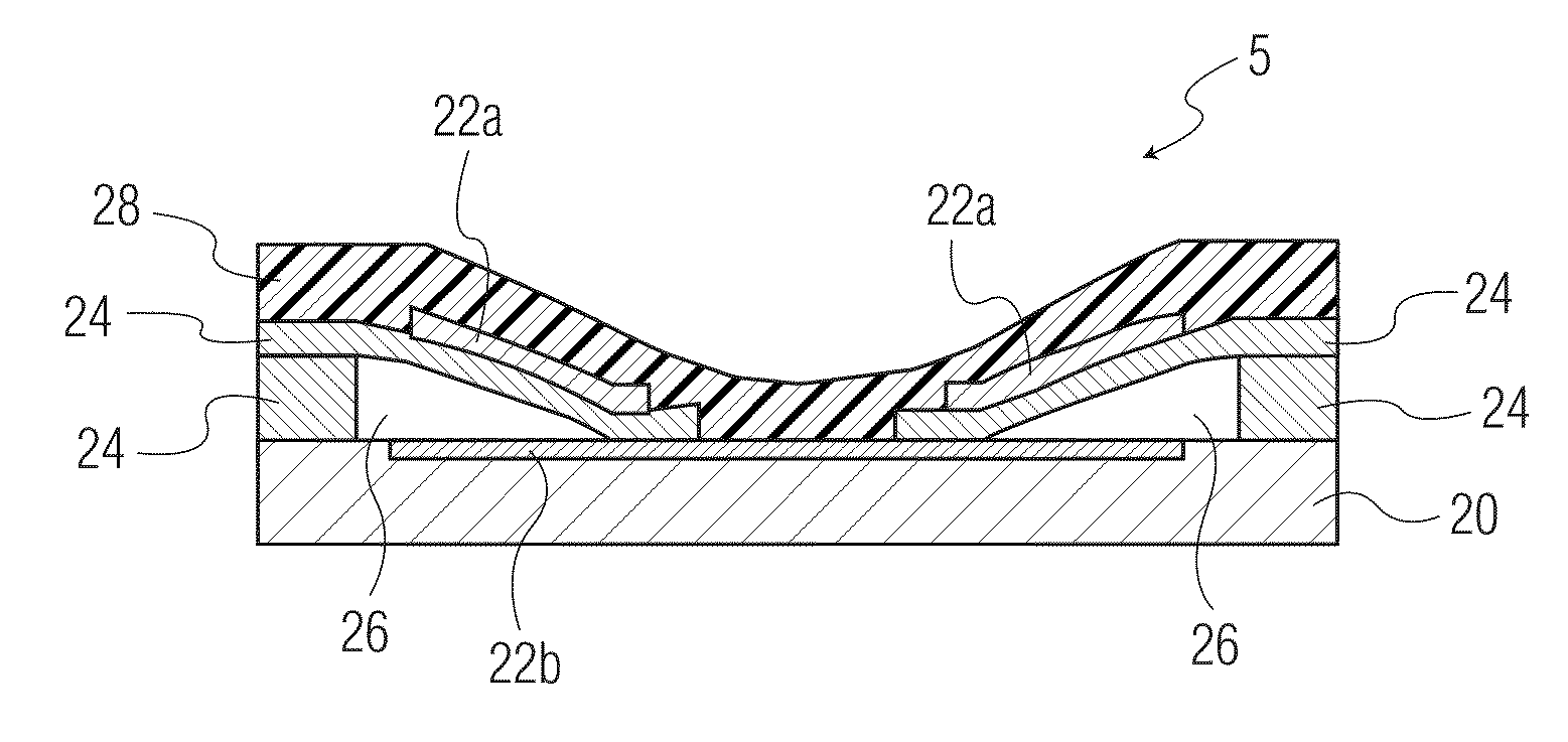
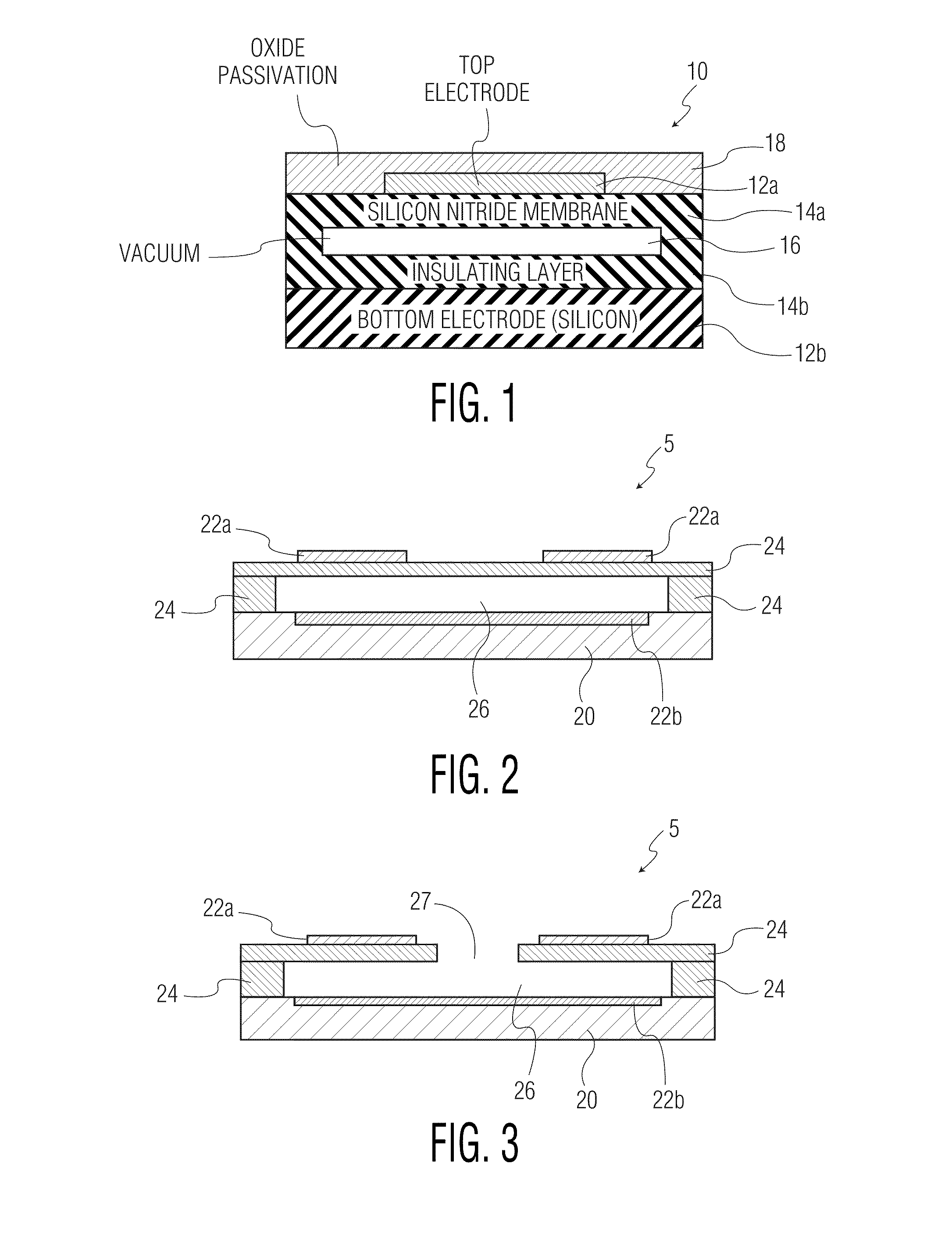
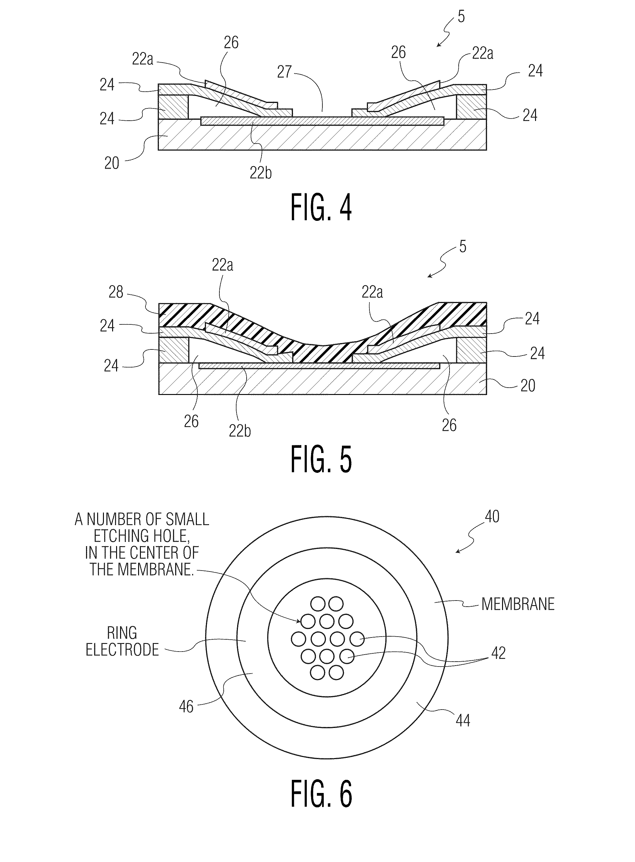
[0041]Exemplary methods for fabrication of collapsed cMUTs according to the present disclosure typically include the following steps: (1) obtaining a nearly completed cMUT as depicted in FIG. 2, (2) defining at least one hole (and optionally a plurality of holes) through the membrane layer for each cMUT element as depicted in FIG. 3, (3) applying a bias voltage across the membrane and substrate layers so as to collapse the membrane layer relative to the substrate layer as depicted in FIG. 4, and (4) fixing and sealing the collapsed membrane layer relative to the substrate layer as depicted in FIG. 5.

[0042]With initial reference to FIG. 2, a schematic cross-section of a cMUT ...


PUM

PropertyMeasurementUnit
DC voltageaaaaaaaaaa
diameteraaaaaaaaaa

Abstract

Methods are provided for production of pre-collapsed capacitive micro-machined ultrasonic transducers (cMUTs). Methods disclosed generally include the steps of obtaining a nearly completed traditional cMUT structure prior to etching and sealing the membrane, defining holes through the membrane of the cMUT structure for each electrode ring fixed relative to the top face of the membrane, applying a bias voltage across the membrane and substrate of the cMUT structure so as to collapse the areas of the membrane proximate to the holes to or toward the substrate, fixing and sealing the collapsed areas of the membrane to the substrate by applying an encasing layer, and discontinuing or reducing the bias voltage. CMUT assemblies are provided, including packaged assemblies, integrated assemblies with an integrated circuit / chip (e.g., a beam-steering chip) and a cMUT / lens assembly. Advantageous cMUT-based applications utilizing the disclosed pre-collapsed cMUTs are also provided, e.g., ultrasound transducer-based applications, catheter-based applications, needle-based applications and flowmeter applications.

Description

BACKGROUND[0001]1. Technical Field[0002]The present disclosure is generally directed towards the field of acoustic imaging, e.g., photoacoustic imaging, ultrasonic imaging, and the like. More particularly, exemplary embodiments of the present disclosure relate to new and useful methods for the production of high-end transducer arrays, e.g., transducer arrays that may be advantageously employed in acoustic imaging applications. Exemplary embodiments of the present disclosure also relate to capacitive micro-machined ultra sonic transducers (cMUTs) that provide improved uniformity and reliability based on the advantageous production methods disclosed herein.[0003]2. Background Art[0004]In acoustic imaging applications, high-end two-dimensional arrays of ultrasound (US) transducers enable active beam steering / focusing and offer / support real-time three-dimensional imaging applications. Furthermore, the quality of such transducer arrays is a key to overall acoustic imaging product perform...

Claims


Application Information

Patent Timeline
Patent Type & Authority Patents(United States)
IPC IPC(8): H04R31/00
CPCA61B8/00B06B1/0292Y10T29/4908Y10T29/43Y10T29/49005H04R19/005
Inventor DIRKSEN, PETERVAN DER LUGT, ANTHONIE
Owner KONINK PHILIPS ELECTRONICS NV
Why Eureka
Try Eureka