Retractable/extendable crank using a cylindrical cam, an end cam, or a swash plate cam, and bicycle using the same

a technology of cylindrical cams and end cams, which is applied in the direction of frictional roller based transmission, steering devices, cycle equipments, etc., can solve the problems of increased manufacturing costs, fatigue and discomfort, and difficult crank rotation, so as to reduce friction, reduce fatigue and discomfort, and rotate smoothly

Inactive Publication Date: 2012-12-11
LEE KEUN HYOUNG
View PDF18 Cites 5 Cited by
  • Summary
  • Abstract
  • Description
  • Claims
  • Application Information

AI Technical Summary

Benefits of technology

[0012]The present invention has been made in an effort to provide a crank rotating a rotary body that achieves large torque by increasing the length of the crank in a force-applying section, easily rotates in a section where force is not applied, by decreasing the length of the crank to reduce the rotational radius, and rotates with ease without making an arm or a leg not deviate from a normal rotation range such that it is not fatigued. The rotation becomes easy by increasing the length to achieve torque by pressing a crank pedal and decreasing the length when torque is not achieved and it idles, in order to use the retractable / extendable crank having the above function for a driving crank of a bicycle.
[0014]In this configuration, it is preferable provide a lubricant or dispose a linear bearing at the rotating parts in order to reduce friction and make smooth sliding, by using bearings or bearing metal.
[0015]The retractable / extendable crank of the present invention can achieve large torque from the same force because the crank extends in a section where force is applied, and can smoothly rotate in a section where force is not applied, because the crank retracts and the rotational radius decreases. Further, an arm or a leg does not deviate from a normal motion range in use due to the decrease of rotational radius, such that the rotation is easily performed and the use is convenient.
[0016]The retractable / extendable crank of the present invention has very simple configuration and operation, such that it is suitable for a driving crank connected to the pedal of a bicycle. A bicycle equipped with the retractable / extendable crank can apply larger torque to a driving unit by using the same-sized driving crank as compared with common bicycles, such that it is possible to more rapidly climb a steeper hill using the same force.
[0017]Further, since the retractable / extendable crank of the present invention has a very simple configuration, such that the size and the weight can be reduced and the manufacturing cost is low. Therefore, it can be simply used for a pedal crank where a pedal of a bicycle is coupled or a rotating handle of a rotary body that is manually operated.

Problems solved by technology

However, although it is possible to achieve larger torque by increasing the length of the crank, the rotational radius correspondingly increases and the arm or leg rotating the rotary body deviates from the normal motion range, which makes the rotation of the crank difficult and causes fatigue and discomfort.
The patent that has proposed a device for rotation of a crank type with a variation length not only is complicated, but has a large number of parts, such that the manufacturing cost increase and it may difficult to be mounted on the existing bicycles.

Method used


Image

  • Retractable/extendable crank using a cylindrical cam, an end cam, or a swash plate cam, and bicycle using the same
  • Retractable/extendable crank using a cylindrical cam, an end cam, or a swash plate cam, and bicycle using the same
  • Retractable/extendable crank using a cylindrical cam, an end cam, or a swash plate cam, and bicycle using the same

Examples


embodiment 1

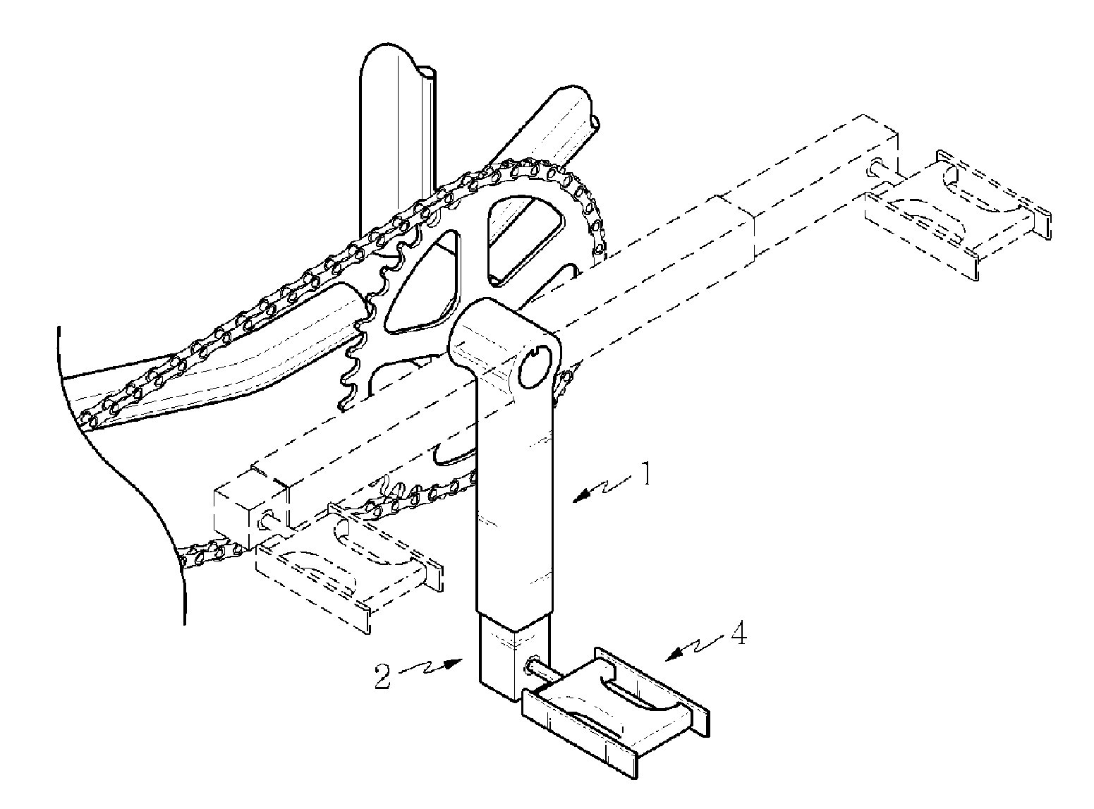
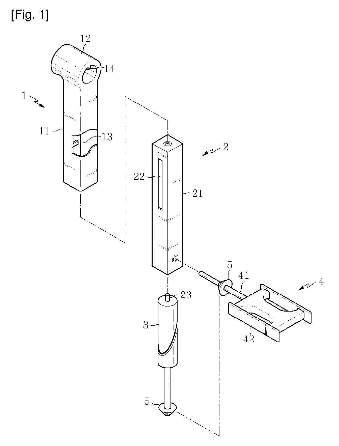
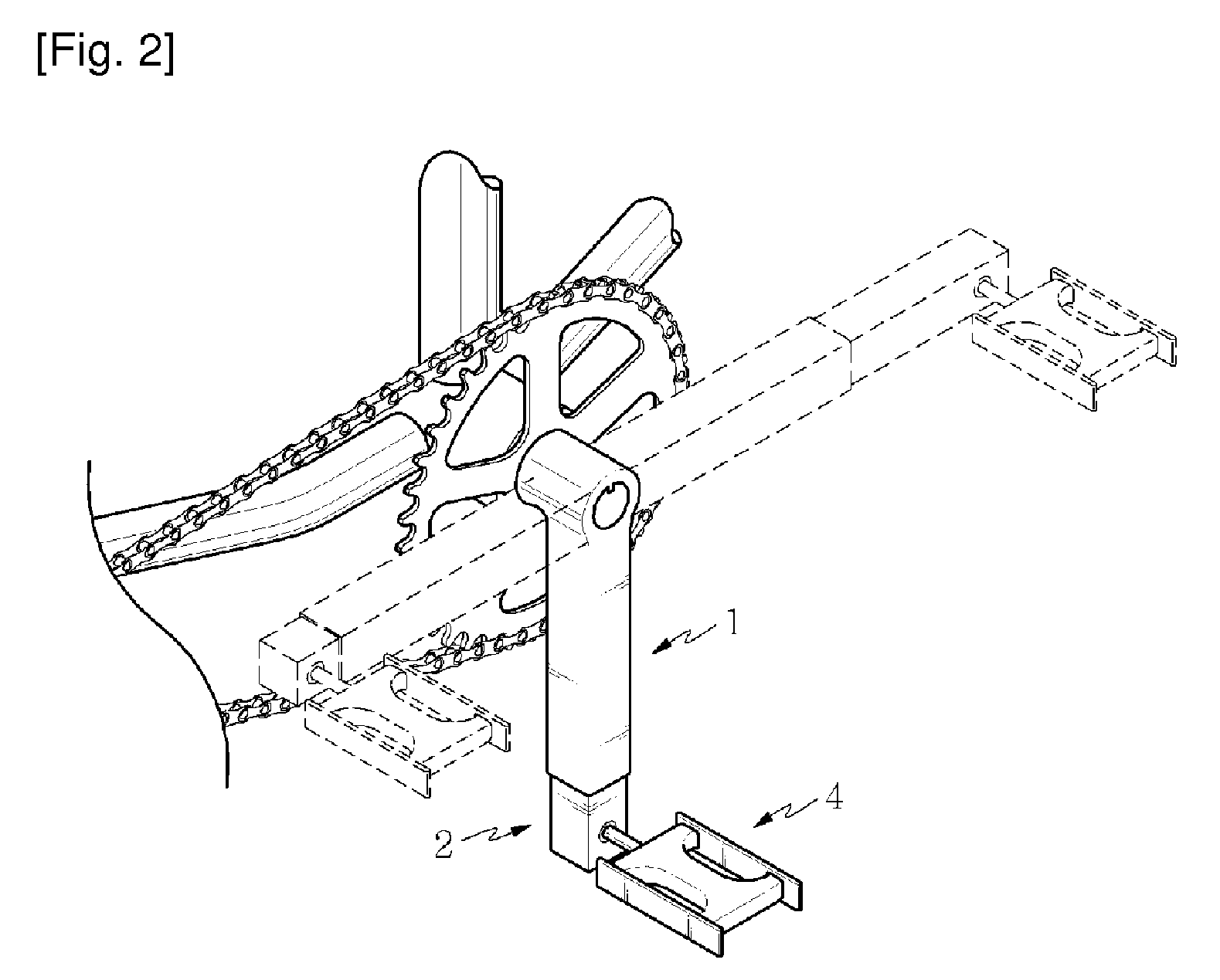
[0026]A retractable / extendable crank using a cylindrical cam, as shown in FIG. 1, includes a crank composed of a fixed arm 1 coupled to a rotary shaft of a rotary body, a crank having a movable arm 2 sliding in the fixed arm 1, a cylindrical cam 3 rotating in the movable arm 2, a pedal 4 connected to an exposed end of the movable arm 2, and a pair of bevel gears 5 fitted on the shaft of the cylindrical cam 3 and the shaft of the pedal 4.

[0027]An example when the retractable / extendable crank using a cylindrical cam having the above configuration according to an exemplary embodiment of the present invention is shown in FIG. 2.

[0028]The fixed arm 1, as shown in FIG. 3, has a fixed arm body 11 having one end with a boss 12 coupled to a rotary shaft and the other end that is bored to insert the movable arm 2 to retract / extend. A cam guide 13 protrudes inward on a side of the fixed arm body 11. The boss 12 of the fixed arm is coupled with the rotary shaft by a key 14 or a spline (not show...

embodiment 2

[0045]The retractable / extendable crank described above may be implemented by an end cam 3-1 or a swash plate cam 3-2, instead of the cylindrical cam 3. A close-contact spring 6 is necessary to keep the cam surface and a cam guide 13 in close contact, in order to use the end cam or the swash plate cam.

[0046]The end cam 3-1 has the shape shown in (a) of FIG. 6 and is a cam that is manufactured by coupling a rotary shaft to a cam body formed by cutting off at an angle one end of a pipe or a cylinder having a definite thickness, and a cam guide 13 is in close contact to the slope. As the end cam 3-1 rotates around the camshaft, the end cam 3-1 is reciprocated by the cam guide 13 fixed to a fixed arm and accordingly a movable arm 2 in the end cam 3-1 retracts / extends while slide-reciprocating.

[0047]The swash plate cam 3-2 has the shape shown in (b) of FIG. 6 and is a cam that is manufactured by coupling a circular swash plate to a rotary shaft at an angle, in which a cam guide 13 is in c...

embodiment 3

[0053]According to another exemplary embodiment of the present invention, a crank uses a cylindrical cam, similar to the Embodiment 1, in which the cylindrical cam is disposed not in the movable arm, but in the fixed arm.

[0054]The retractable / extendable crank using a cylindrical cam according to this exemplary embodiment, as shown in FIG. 7, includes a crank composed of a fixed arm 1-1 coupled to a rotary shaft of a rotary body and a movable arm 2-1 sliding outside the fixed arm 1-1, a cylindrical cam 3-1 rotating in the fixed arm 1-1, a pedal (not shown) coupled to the end of the movable arm 2-1, and a pair of bevel gears 5 assembled on the shaft of the cylindrical cam 3-1 and the shaft of the pedal, respectively.

[0055]In the fixed arm 1-1, similar to that of the Embodiment 1, a boss 12-1 fitted on a rotary shaft is formed at one end of a fixed arm body 11-1 and the other end of the fixed arm body 11-1 is inserted in the movable arm 2-1, a cylindrical cam hole 16-1 is formed therei...


PUM


Abstract

The present invention relates to a mechanical element, and more particularly, to a crank connected to a bicycle pedal or a handle for rotating a rotary body and to a bicycle using the same. The present invention uses a cylindrical cam, an end cam, or a swash plate cam, and the shafts of these cams and a shaft of a pedal or a handle for applying force are equipped with a miter gear (a bevel gear the number of teeth of which is 1:1 and the shaft angle of which is 90 degrees), such that the crank retracts / extends one time per one rotation of the pedal or the handle.

Description

RELATED APPLICATIONS[0001]This application is a 371 application of International Application No. PCT / KR2009 / 003629, filed Jul. 2, 2009, which in turn claims priority from Korean Patent Application Nos. 10-2009-0056557, filed Jun. 24, 2009; 10-2008-0121047, filed Dec. 2, 2008; and 10-2008-0070058, filed Jul. 18, 2008, each of which is incorporated herein by reference in its entirety.BACKGROUND OF THE INVENTION[0002]1. Field of the Invention[0003]The present invention relates to a mechanical element, in more detail, a crank connected to a pedal of a bicycle or a crank connected to a handle rotating rotary body, and a bicycle using the crank.[0004]2. Description of the Related Art[0005]One end of a crank rotating a rotary body is fixed to the shaft of a rotating body and the other end is connected to a member applying force to a handle and a pedal etc. Torque T rotating the rotary body is calculated by multiplying the length of the crank which corresponds to an arm length, that is, (by...

Claims


Application Information

Patent Timeline
Patent Type & Authority Patents(United States)
IPC IPC(8): B62M1/02B62M3/00B62M1/36
CPCB62M3/04B62M3/06Y10T74/2165Y10T74/2167B62K19/34B62M1/10B62M3/02
Inventor LEE, KEUN HYOUNG
Owner LEE KEUN HYOUNG
Why Eureka
Try Eureka