Spread-spectrum high-frequency heating device

a heating device and high-frequency technology, applied in the field of rf heating system, can solve the problems of easy damage of the semiconductor power amplifier, and achieve the effect of reducing the size and cost of the heating system, facilitating the heating process, and ensuring the optimal heating process conditions

Active Publication Date: 2012-12-11
PANASONIC CORP
View PDF12 Cites 18 Cited by
  • Summary
  • Abstract
  • Description
  • Claims
  • Application Information

AI Technical Summary

Benefits of technology

[0035]According to the present invention, the frequency that will lead to the lowest intensity of the reflected wave (i.e., the reflection power) is detected by frequency hopping. Thus, there is no need to perform the monitor mode operation with low power, and therefore, the heating process can get done in a shorter time. Also, even if the condition of the object in the heating chamber changed with time, the heating process conditions can always be optimized by performing that frequency hopping during the heating process. That is to say, according to the present invention, the heating process is not performed continuously at a frequency at which the reflected wave has a local minimum intensity but hopping is done from such a frequency at which the reflected wave has a local minimum intensity to another frequency at which the reflected wave does not have a local minimum intensity in the middle of the heating process.
[0036]By getting that frequency hopping done a number of times at short intervals, the electromagnetic wave is never radiated for a long time at such a frequency at which the reflected wave has a high intensity, thus preventing the semiconductor power amplifier from getting damaged by an intense reflected wave. On top of that, there is no need to provide an isolator anymore in order to protect the environment from the reflected waves. As a result, the size and cost of the heating system can be reduced. Added to that, since the distribution of the electromagnetic field in the heating chamber can be changed by that frequency hopping, the object can be heated uniformly even without stirring up radio waves or using a turntable.
[0037]In an embodiment in which a single RF heating system includes multiple lines of power amplifiers and radiators, the radiation frequencies can be changed so as to have no correlation at all between those lines. As a result, the reflected waves of the respective lines can be monitored accurately. On top of that, the heating process can get done with reduced power dissipation, thus saving a lot of energy efficiently.
[0038]What is more, the RF heating system of the present invention does not use any magnetron, and therefore, each radiation spectrum is narrow enough to be adjusted appropriately to its proper permissible radiation range. As a result, the electromagnetic compatibility (EMC) can be improved, and the overall cost can be cut down, too, because a number of parts that would otherwise be needed to improve the EMC can be omitted according to the present invention.

Problems solved by technology

However, a semiconductor power amplifier would be easily damaged under the heat when exposed to an intense reflected wave, which is a serious problem that must be solved to actually use it in that field of applications.

Method used


Image

  • Spread-spectrum high-frequency heating device
  • Spread-spectrum high-frequency heating device
  • Spread-spectrum high-frequency heating device

Examples


embodiment 1

[0066]Hereinafter, a first specific preferred embodiment of an RF heating system according to the present invention will be described.

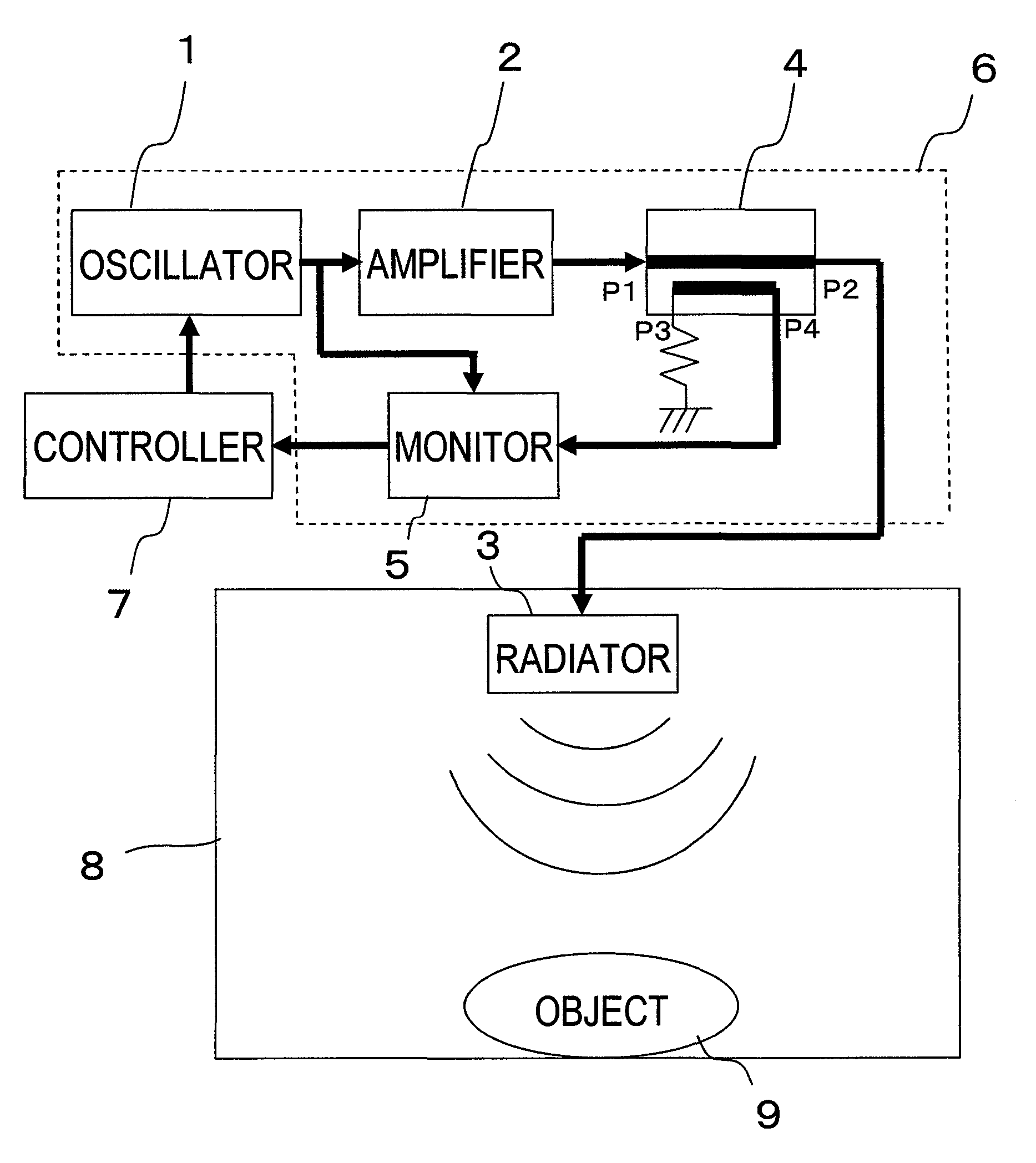
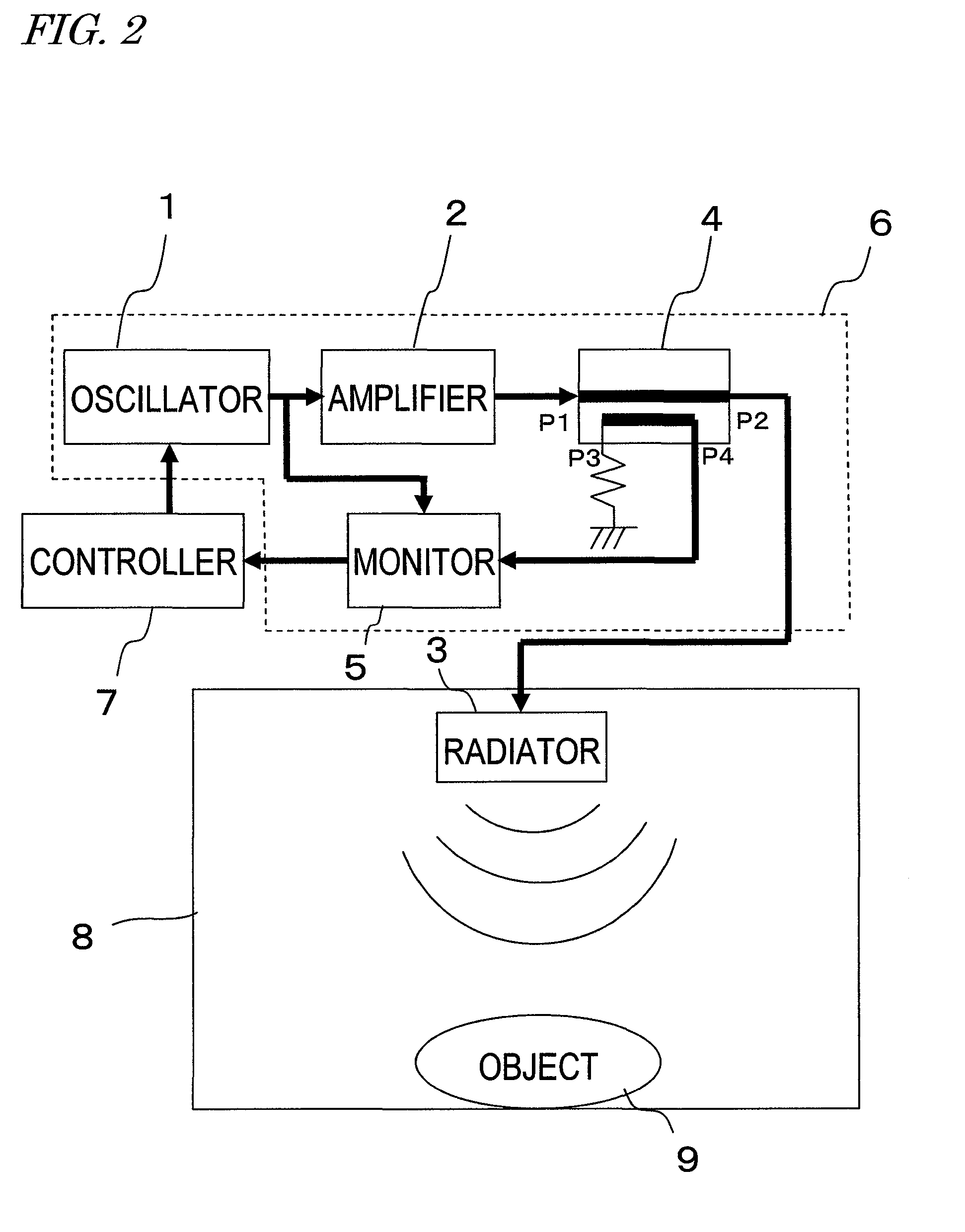
[0067]First of all, look at FIG. 2, which is a block diagram illustrating an RF heating system as a first preferred embodiment of the present invention. The RF heating system shown in FIG. 2 includes a variable-frequency oscillator 1, a semiconductor power amplifier 2 for amplifying the output of the variable-frequency oscillator 1, a radiator 3 for radiating an electromagnetic wave for heating based on the output of the semiconductor power amplifier 2, a reflected wave monitoring circuit 5 for detecting a reflected wave of the electromagnetic wave for heating, and a controller 7 for controlling the oscillation frequency of the variable-frequency oscillator 1. The controller 7 changes the oscillation frequencies of the variable-frequency oscillator 1 discontinuously, thereby getting frequency-hopping spread-spectrum radiation done by the radiator 3. T...

embodiment 2

[0108]Hereinafter, a second preferred embodiment of an RF heating system according to the present invention will be described with reference to FIG. 8, which is a block diagram illustrating a configuration for the RF heating system of the second preferred embodiment.

[0109]As shown in FIG. 8, the RF heating system of this preferred embodiment includes a number of radiating circuits 6, each including the variable-frequency oscillator 1, the semiconductor power amplifier 2, the directional coupler 4 and the reflected wave monitoring circuit 5. Also, each of those radiating circuits 6 is coupled to its associated radiator 3. Those radiators 3 are preferably arranged on mutually different wall surfaces of the same heating chamber 8 and preferably face the object 9 to be heated 9 in the heating chamber 8 at significantly different angles. Each of these components has basically the same structure, and operates in substantially the same way, as its counterpart of the first preferred embodim...


PUM


Abstract

A variable-frequency oscillator 1, a semiconductor power amplifier 2 for amplifying the output of the variable-frequency oscillator 1; a radiator 3 for radiating an electromagnetic wave for heating based on the output of the semiconductor power amplifier 2; a reflected wave monitoring circuit 5 for detecting a reflected wave of the electromagnetic wave for heating; and a controller 7 for controlling the oscillation frequency of the variable-frequency oscillator 1 are provided. The controller 7 changes the oscillation frequencies of the variable-frequency oscillator 1 discontinuously, thereby getting a frequency-hopping spread-spectrum radiation done by the radiator 3. The electromagnetic wave radiated by the radiator 3 irradiates an object 9 to be heated (which is usually food) inside a heating chamber 8, thereby heating the object.

Description

TECHNICAL FIELD[0001]The resent invention relates to an RF heating system for use in a microwave oven, for example.BACKGROUND ART[0002]A conventional RF heating system for use in a microwave oven includes a high power direct oscillator device called “magnetron”, which uses a vacuum tube, and an antenna (or radiator) for radiating the electromagnetic wave that is generated by the magnetron inside the heating chamber. The frequencies of electromagnetic waves for such RF heating usually fall within an ISM band, and the oscillation frequency of the magnetron is ordinarily defined to be a predetermined value falling within the range of 2.40 GHz through 2.50 GHz. Actually, however, the oscillation frequency of the magnetron will fluctuate according to the voltage applied to the magnetron and the impedance inside the heating chamber. As a result, the spectrum of its oscillation will eventually cover almost the entire 100 MHz range from 2.40 GHz through 2.50 GHz.[0003]To overcome such a pro...

Claims


Application Information

Patent Timeline
Patent Type & Authority Patents(United States)
IPC IPC(8): H05B6/68
CPCH05B6/686H05B6/705Y02B40/146Y02B40/143Y02B40/00
Inventor ISHIZAKI, TOSHIOOKAJIMA, TOSHIYUKIYAHATA, KAZUHIROUNO, TAKASHI
Owner PANASONIC CORP
Why Eureka
Try Eureka