
Planar optical waveguide with core of low-index-of-refraction interrogation medium

a technology of low-index of refraction and interrogation medium, which is applied in the direction of optical radiation measurement, luminescent dosimeters, instruments, etc., can solve the problems of reducing the evanescent field strength down the length of the waveguide, spatially varying field strength, and single-mode planar waveguides are expensive to manufacture, so as to reduce the inadvertent misalignment of users and reduce the cost of manufacturing. , the effect o

Active Publication Date: 2012-12-11
MBIO DIAGNOSTICS
View PDF98 Cites 15 Cited by
  • Summary
  • Abstract
  • Description
  • Claims
  • Application Information

AI Technical Summary

Benefits of technology

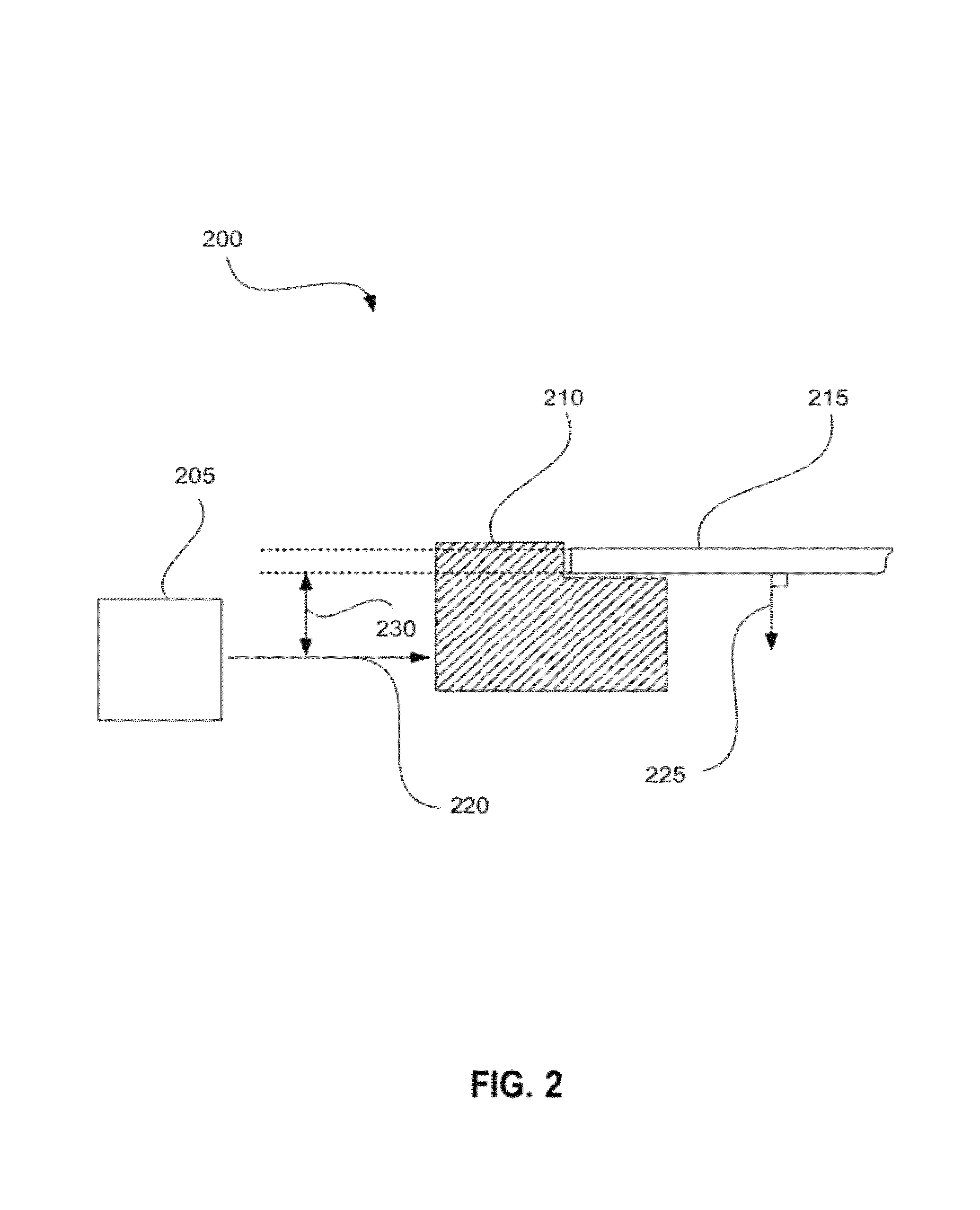
[0016]Embodiments disclosed below allow light to be coupled to a planar waveguide providing a strong evanescent field for sample illumination, while eliminating or greatly reducing inadvertent misalignment by a user. The various embodiments further allow facile tuning of the internal propagation angle inside the waveguide, providing simple adjustment of evanescent field strength. Another embodiment also provides apparatus for performing assays involving placement of a fluidic chamber on a planar waveguide in a manner that is insensitive to the optical properties of the chamber.

Problems solved by technology

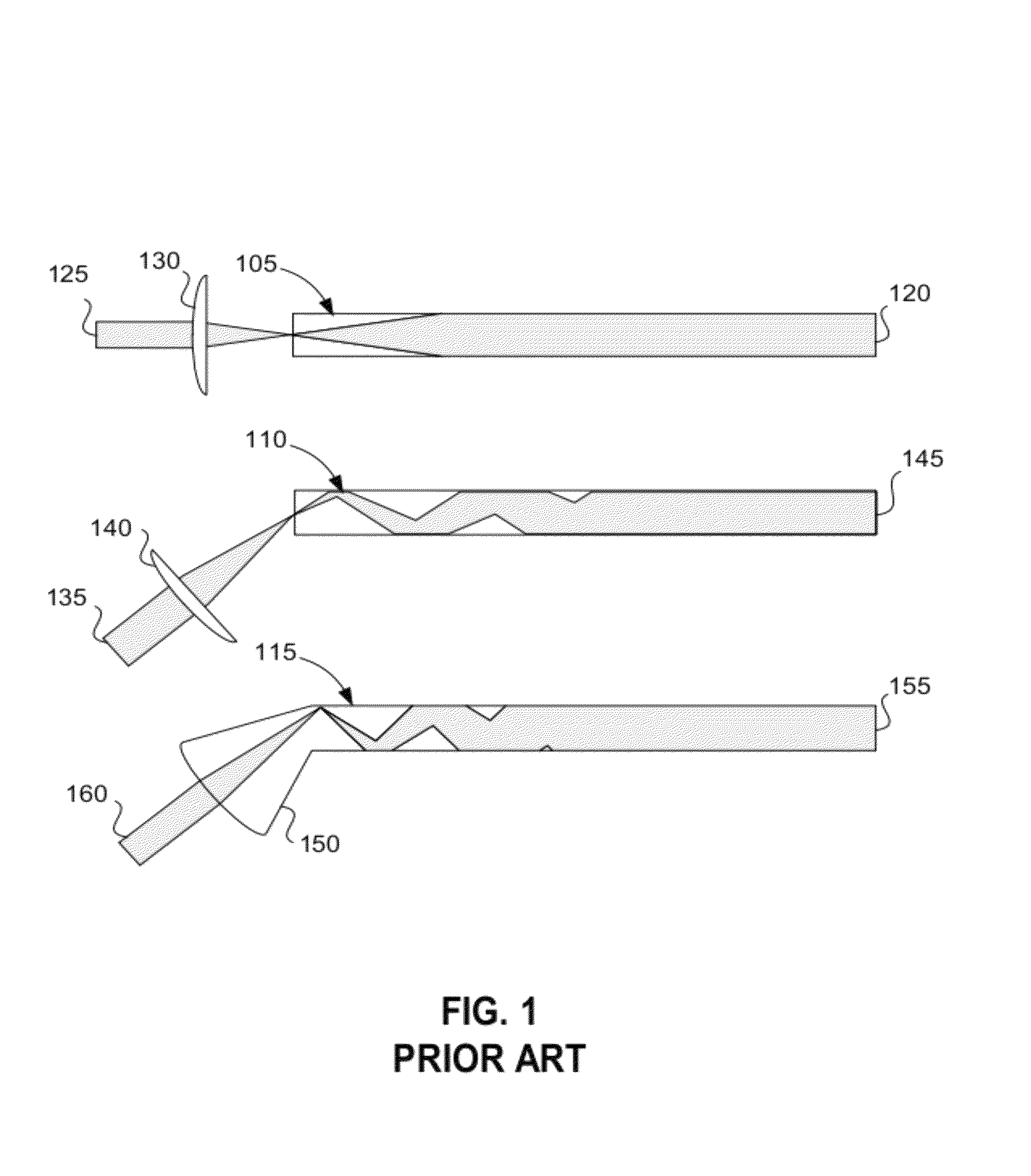
A disadvantage of single-mode waveguides is that for efficient light coupling, they typically require a prism or grating with precise alignment tolerances.
In addition, single-mode planar waveguides are expensive to manufacture because the guiding layer is typically a thin-film with strict thickness tolerances deposited on a substrate.
For a disposable clinical device, however, cost, robustness, and ease of use are of similar importance.
While each individual mode in a multimode waveguide has a uniform intensity along the direction of propagation, a distribution of modes will be excited when coupling to a multimode waveguide; this distribution of modes will constructively and destructively interfere on the surface and lead to a spatially varying field strength.
If the beam is highly focused, however, then the surface intensity normalizes in very few reflections, but a significant amount of power is contained in rays propagating outside the critical angle and leads to reduced evanescent field strength down the length of the waveguide.
On the other hand, when the object of interest, such as a cell or the bulk of a solution, extends substantially beyond the penetration depth of the evanescent wave, evanescent illumination can be less effective than floodlight-type illumination.
However, in practice, waveguiding in a liquid sample contained in another material is difficult due to the fact that common liquids have lower refractive indices than common solids; for example, water has a refractive index of approximately 1.33, while most solid materials have an index of refraction of 1.4 or more.
In interference-based optofluidic waveguides, light is confined to a liquid core by reflection from surrounding materials including two or more layers of higher-index materials combined to result in a lower effective refractive index for the surrounding media.

Method used


Image

  • Planar optical waveguide with core of low-index-of-refraction interrogation medium
  • Planar optical waveguide with core of low-index-of-refraction interrogation medium
  • Planar optical waveguide with core of low-index-of-refraction interrogation medium

Examples


example i

Detection of Fluorescently Labeled Human Blood Cells

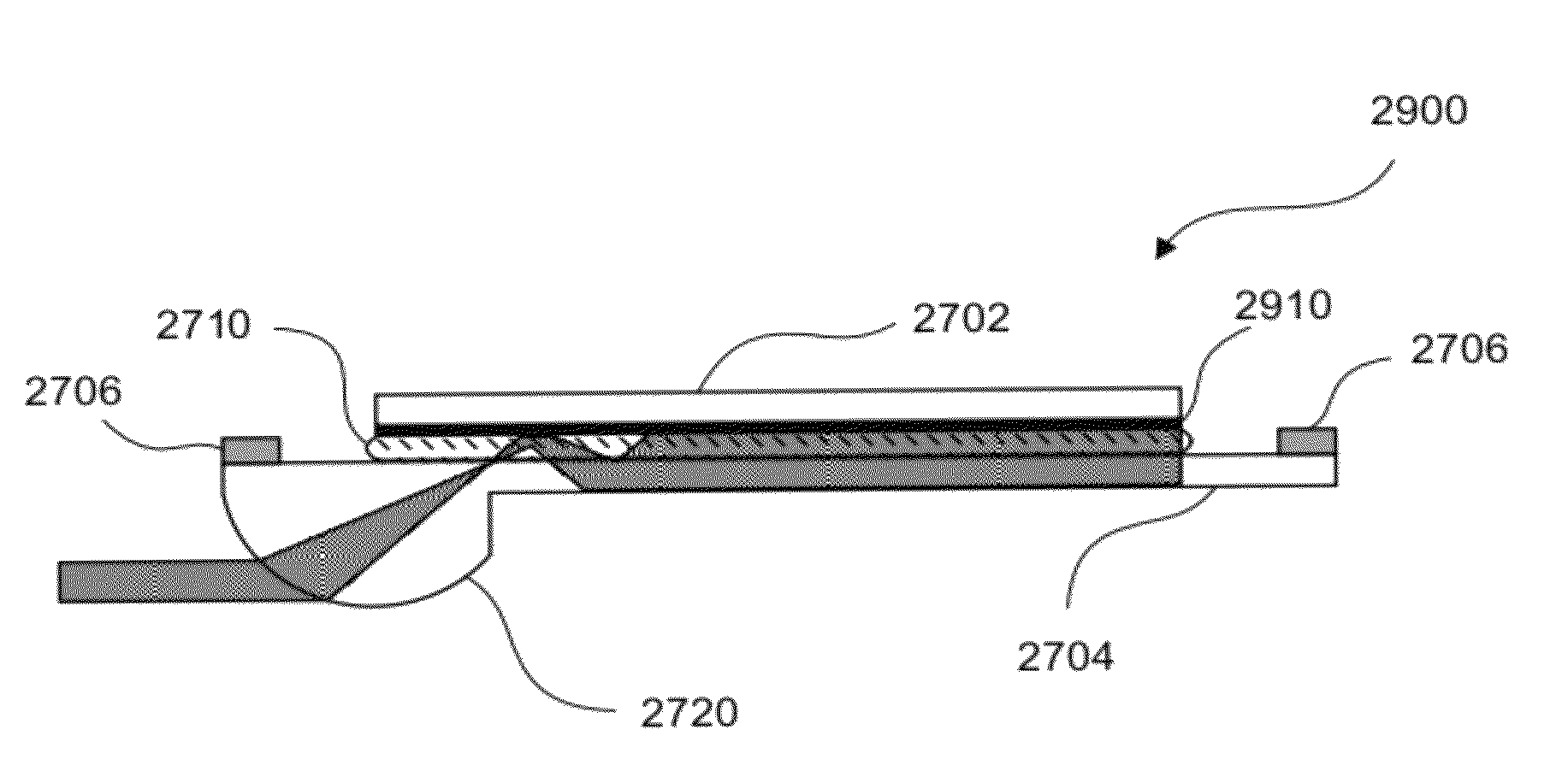
[0095]Human peripheral blood mononucleocytes (“PBMCs”) are labeled with CD3 Alexa Fluor 647 fluorescence stain, available from Invitrogen Corporation. The cells, whose diameter is 6-12 μm, are kept in a buffer consisting of phosphate buffered saline with 1% Bovine Serum Albumin and 0.06% sodium azide. The buffer with cells is loaded into a cartridge of the type shown in FIGS. 27 and 28. The substrate materials and the buffer lead to a critical angle at the substrate-to-interrogation medium interface of θc=61°. 635 nm laser light is coupled into the system through the curved part of the lower substrate. The curvature is designed such that different entry heights result in different angles of incidence onto the substrate-to-interrogation medium interface. Two different laser heights were used in the present example resulting in two different angles of incidence onto the substrate-to-interrogation medium interface: (a) 57° and (b) 66°...


PUM


Abstract

An apparatus for illuminating a sample includes a planar waveguide. The planar waveguide includes a first substrate, including a first outer surface and a first inner surface, and a second substrate, including a second outer surface and a second inner surface. The first and second inner surfaces of the first and second substrates, respectively, are spaced apart from each other and partly define a volume for confining the sample therein. The apparatus also includes a light source for providing light directed toward the planar waveguide, such that the light is optically coupled to and contained within the planar waveguide between the outer surfaces of the first and second substrates, while illuminating at least a portion of the sample confined within the volume.

Description

CROSS REFERENCE TO RELATED APPLICATIONS[0001]The present application is a Continuation of U.S. patent application Ser. No. 12 / 883,724, filed on Sep. 16, 2010, entitled PLANAR OPTICAL WAVEGUIDE WITH CORE OF LOW-INDEX-OF-REFRACTION INTERROGATION MEDIUM, which is a Continuation-in-Part of U.S. patent application Ser. No. 12 / 617,535, filed on Nov. 12, 2009, entitled WAVEGUIDE WITH INTEGRATED LENS, which claims priority to U.S. Provisional Patent Application Ser. No. 61 / 156,586, filed on Mar. 2, 2009, entitled WAVEGUIDE WITH INTEGRATED LENS, all of which are incorporated by reference in their entireties into the present application.GOVERNMENT INTEREST[0002]This research was funded in part by government support under the U.S. Department of Commerce National Institute of Standards (NIST) Advanced Technology Program (ATP), award number 70NANB7H7053. The Government has certain rights in this invention.BACKGROUND[0003]Fluorescently labeled probes provide a convenient method of characterizing ...

Claims


Application Information

Patent Timeline
Patent Type & Authority Patents(United States)
IPC IPC(8): G02B6/10
CPCG01N21/552G02B6/124G02B6/4206
Inventor DELANEY, MARIE J.MOLL, KEVIN D.
Owner MBIO DIAGNOSTICS
Learn More