Outlet guide vanes for axial flow fans

a technology of axial flow fans and guide vanes, which is applied in the direction of machines/engines, stators, liquid fuel engines, etc., can solve the problems of reducing fan efficiency, limitation of operating range, excessive loading and flow separation in the outboard station of stator vanes, etc., to maximize static pressure recovery and minimize flow losses

Active Publication Date: 2012-12-18
CARRIER CORP
View PDF13 Cites 18 Cited by
  • Summary
  • Abstract
  • Description
  • Claims
  • Application Information

AI Technical Summary

Benefits of technology

[0014]In accordance with another aspect of the invention vane stagger angle and vane chord are locally increased over the outer one-fourth span portion. These features allow the stator vanes to address the strong localized swirl flow that originates in the clearance flow of the upstream rotor to thereby minimize flow losses within the vane system and maximize static pressure recovery.

Problems solved by technology

This localized swirl is especially important in fans with low ratio of axial flow velocity relative to blade tip speed (low flow coefficient), and can produce excessive loading and flow separation in the outboard stations of the stator vanes.
Use of conventional guide vane design in such cases produces reduced fan efficiency and limitations in operating range.

Method used


Image

  • Outlet guide vanes for axial flow fans
  • Outlet guide vanes for axial flow fans
  • Outlet guide vanes for axial flow fans

Examples


Embodiment Construction

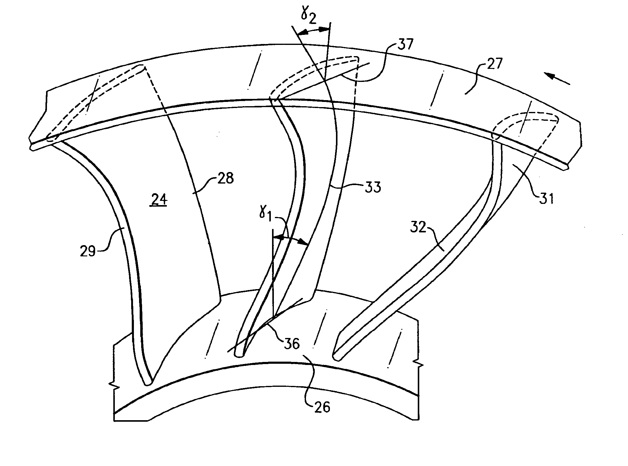
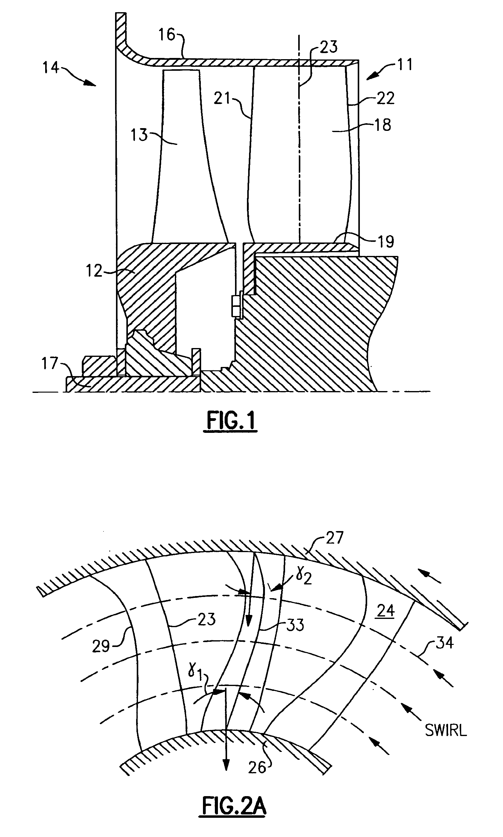
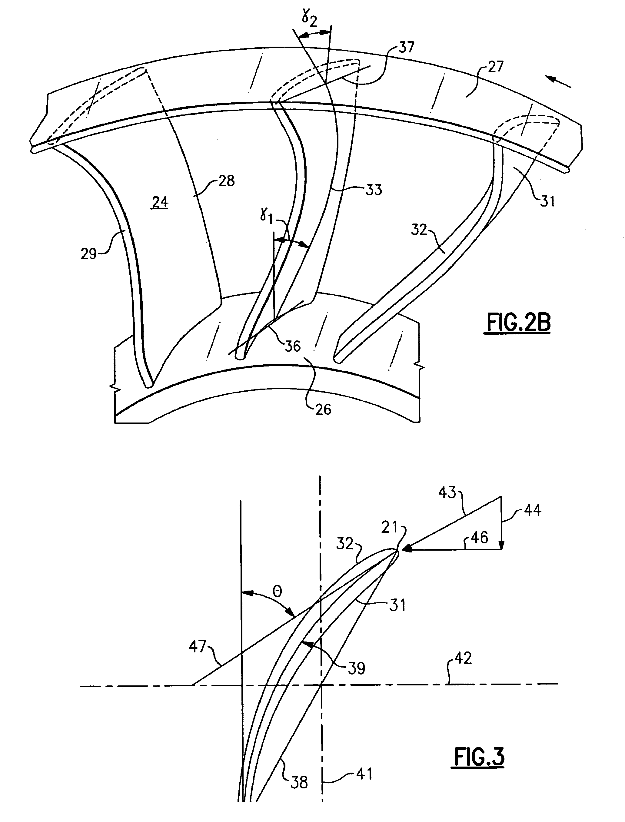
[0023]An axial flow fan assembly is shown generally at 11 which includes a fan rotor 12 and a plurality of fan blades 13 attached to its outer periphery and extending radially outwardly into an opening 14 which is defined on its radially outer side by a casing 16. A drive motor 17 rotates the fan rotor 12 and its attached fan blades 13 to cause air to be drawn in and passed through the opening 14. Located downstream of the fan blades 13 is a plurality of outlet guide vanes 18 which are secured at their radially inner ends to an inner end wall 19 and at their radially outer ends to the casing 16 as shown. The outlet guide vanes 18 have a leading edge 21 and a trailing edge 22. The line 23 is drawn to connect the mid points between the leading edge 21 and 22 at constant radius stations, as indicated by the dashed lines, and is commonly known as the vane stacking axis. It should be recognized that the vane stacking axis 23 is linear and is orientated in the radial direction as shown.

[0...


PUM


Abstract

An outlet guide vane system is disclosed for axial flow fans. Construction details are described which reduce losses in the end wall regions of the vanes, particularly for axial flow fans operating at low flow coefficient with strong localized swirl associated with upstream rotor tip clearance flows. In the preferred embodiment, the vane spanwise airfoil stacking line is approximately straight, while leaning circumferentially toward the incoming swirl flow over the majority of the radial span. The stacking line then curves abruptly in the opposite direction over the radially outboard spanwise portion, so as to lean away from the incoming swirl at the vane tip station. The radially outboard portion of the vanes simultaneously include a gradual increase in vane stagger angle, vane camber angle and vane chord. The vane may also include an axial sweep component.

Description

BACKGROUND OF THE INVENTION[0001]This invention relates generally to fans for moving air and, more particularly, to an improved outlet guide vane design for axial flow fans.[0002]Axial flow fans are used in a wide range of applications, including HVAC, refrigeration, automotive, power systems and aerospace. Important considerations for these applications include efficiency, noise level, operating range, compactness, reliability and cost.[0003]High performance axial flow fans typically utilize stationary outlet guide vanes to recover swirl flow generated by the upstream fan blades. This recovery process involves the transformation of swirl kinetic energy into increased static pressure across the guide vanes, and leads to significant improvement in efficiency. To achieve effective performance, care must be taken to design the vanes to be well aligned with the oncoming swirl and to ensure that they are able to turn the flow back to the axial direction with minimal total pressure loss.[...

Claims


Application Information

Patent Timeline
Patent Type & Authority Patents(United States)
IPC IPC(8): F01D9/00
CPCF04D29/544
Inventor BUSHNELL, PETER R.
Owner CARRIER CORP
Why Eureka
Try Eureka