Irrigated catheter with improved irrigation flow

a technology of irrigated catheters and nozzles, which is applied in the field of irrigated catheters, can solve the problems of limited power delivery, increased pressure, and inability to provide uniform fluid distribution along the outer surface of the tip electrode, so as to improve the cooling and flushing of blood, improve the effect of heat transfer and large lesions

Active Publication Date: 2012-12-18
BIOSENSE WEBSTER INC
View PDF13 Cites 49 Cited by
  • Summary
  • Abstract
  • Description
  • Claims
  • Application Information

AI Technical Summary

Benefits of technology

[0009]The present invention is directed to an irrigated ablation catheter that provides improved distribution of irrigation fluid across its tip electrode surface resulting in improved cooling and flushing of blood and proteins from the tip region. An axially directed flow of irrigation provides improved heat transfer from the tip electrode to the irrigation fluid allowing for a cooler tip electrode and larger lesions.
[0011]The flow directing member is intended to evenly distribute the irrigation flow over the tip electrode, thus providing several benefits, including improved flushing of blood from the tip electrode surface and improved convective cooling of the tip electrode and tissue-to-tip electrode interface.
[0012]Improved flushing of blood from the tip electrode can more efficiently reduce or eliminate formation of coagulation on the tip electrode associated with the denaturing of proteins during RF application. By creating a generally uniform boundary layer of irrigation fluid around the tip electrode, blood is kept from the tip electrode or it is diluted such that the quantity of proteins exposed to high heat levels during RF ablation is significantly decreased. Additionally, the generally uniform flow of irrigation fluid along the tip electrode tends to ensure that blood or blood protein contact with heat is momentary.
[0013]The catheter increases heat loss including convective heat loss by the tip electrode to the irrigation fluid by containing the irrigation fluid along the outer surface of the proximal portion of the tip electrode. By using the outer surface of the trip electrode as the cooling interface rather than internal cooling channels, the convective heat loss can be greatly increased due to the larger surface area provided by the outer surface of the tip electrode. It is also contemplated that the outer surface 63 can be texturized or roughen (see FIG. 6A) to increase the surface area for further increased convective heat loss. Heat fins 65 (see FIG. 6B) can also be added to the tip electrode for further increased convective heat loss. The flow directing member is configured to also direct the fluid along the distal end of the tip selectrode providing for additional convective heat loss.
[0014]During RF application, the improved fluid flow along the tip electrode provides more efficient convective heat loss, which could lead to a lower fluid flow rate and thus a decrease in delivery of fluid to the ablation site over the course of the procedure. In one embodiment, the catheter has a catheter body and a tip section adapted for ablation and irrigation. The tip section has a tip electrode and a flow directing member positioned over the tip electrode to direct fluid to flow over an outer surface of the tip electrode. The flow directing member is tubular having an inner surface that is supported away from the outer surface of the tip electrode by ribs extending longitudinally along the inner surface of the flow directing member. Gaps formed by the ribs define fluid channels that guide the fluid to flow over the outer surface of the tip electrode.
[0015]In a more detailed embodiment, the tip section also has a fluid cavity immediately proximal the tip electrode wherein fluid fed by the catheter body enters the cavity to come in contact with the outer surface of the tip electrode. To protect components extending through the cavity and into the tip electrode, connective tube are provided to bridge the cavity and isolate the components from exposure to the fluid. One or more connective tubes are notched at their distal end to prevent the distal end from cutting into the components, particularly those extending at an angle to the connective tubes.

Problems solved by technology

This can cause an impedance rise and / or a thrombus that could become an embolus.
When RF current is applied to an ablation electrode in good contact with the endocardium to create a lesion, the amount of power delivered is limited by the heating of the electrode in order to prevent char and thrombus.
These designs do not provide uniform fluid distribution along the outer surface of the tip electrodes.
Additionally, the irrigation fluid is projected far from the tip electrode and does not provide a uniform and complete boundary layer from the surrounding blood.

Method used


Image

  • Irrigated catheter with improved irrigation flow
  • Irrigated catheter with improved irrigation flow
  • Irrigated catheter with improved irrigation flow

Examples


Embodiment Construction

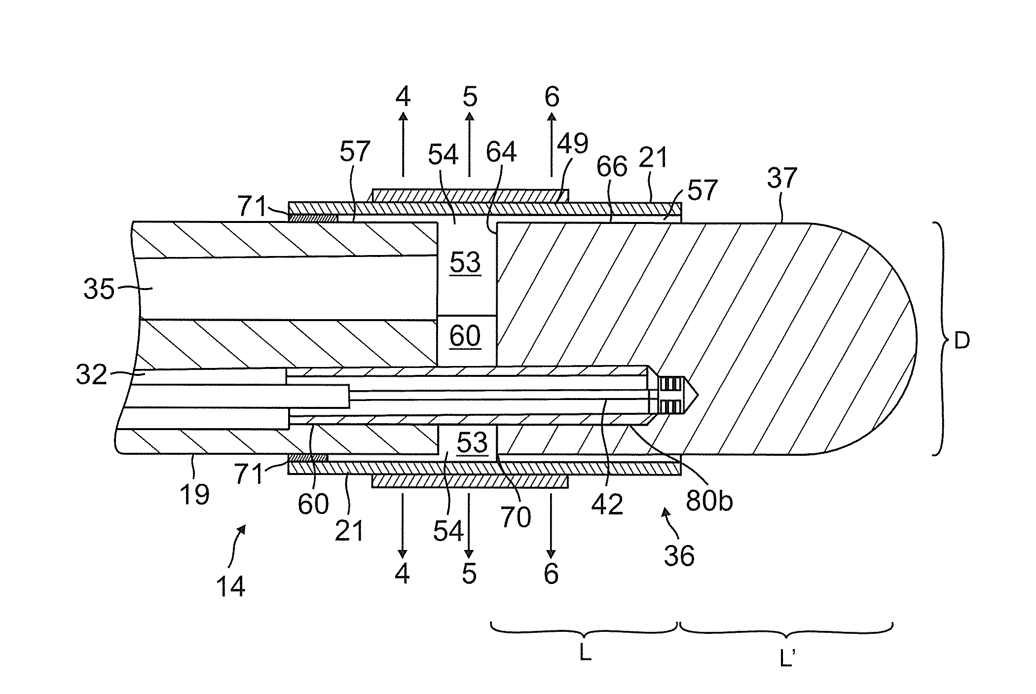
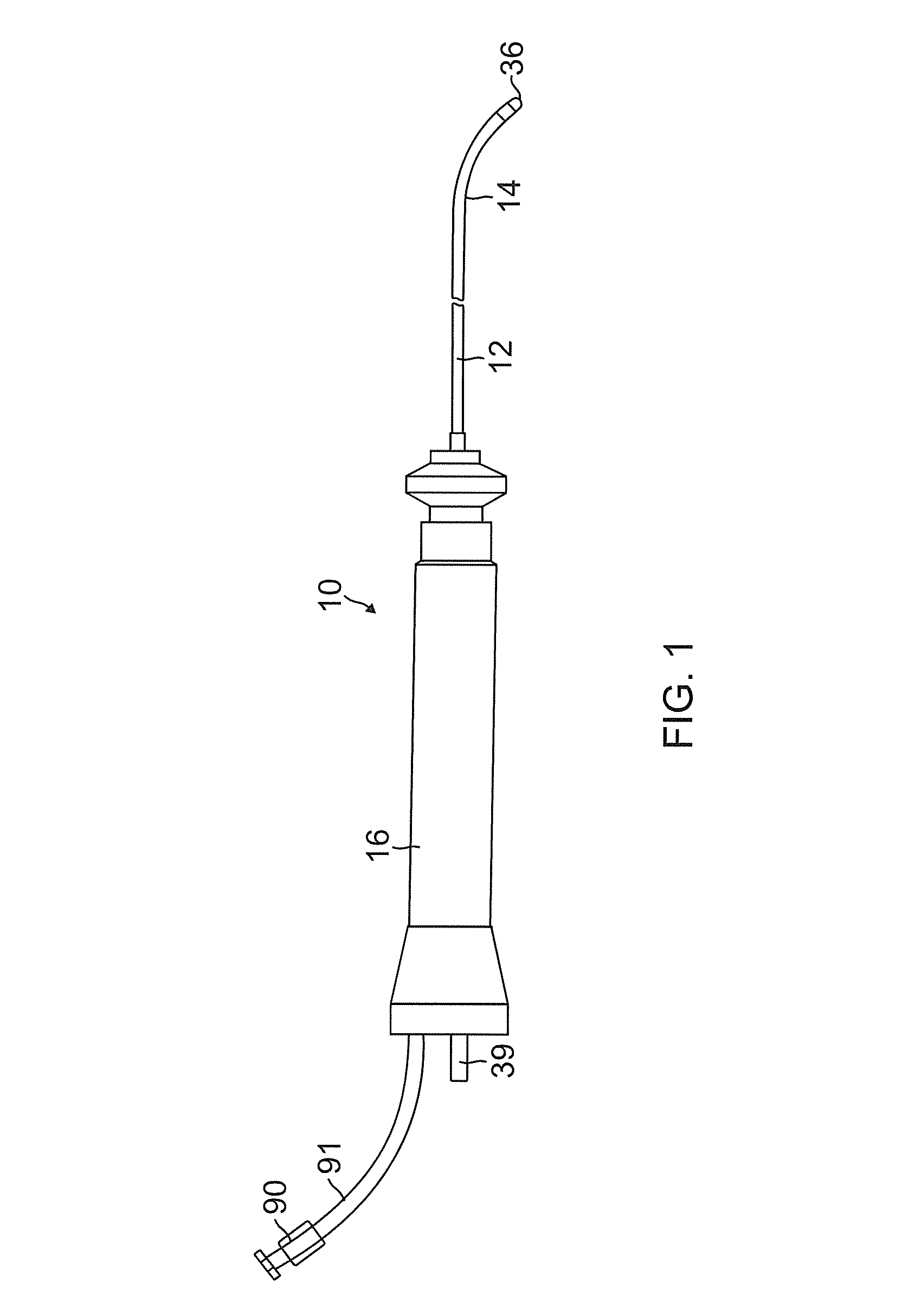
[0037]As shown in FIGS. 1-8 catheter 10 of the present invention comprises an elongated catheter body 12 having proximal and distal ends, a deflectable (uni- or bi-directionally) intermediate section 14 at the distal end of the catheter body 12, a tip section 36 at the distal end of the intermediate section, and a control handle 16 at the proximal end of the catheter body 12.

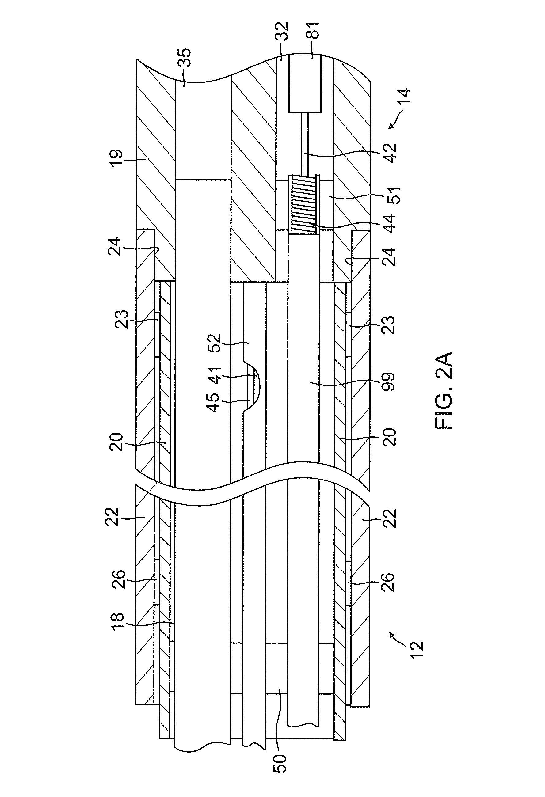
[0038]With additional reference to FIGS. 2A and 2B, the catheter body 12 comprises an elongated tubular construction having a single, axial or central lumen 18. The catheter body 12 is flexible, i.e., bendable, but substantially non-compressible along its length. The catheter body 12 can be of any suitable construction and made of any suitable material. A construction comprises an outer wall 22 made of an extruded plastic. The outer wall 22 may comprise an imbedded braided mesh of stainless steel or the like to increase torsional stiffness of the catheter body 12 so that, when the control handle 16 is rotated, t...


PUM


Abstract

An irrigated ablation catheter provides improved distribution of irrigation fluid across its tip electrode surface resulting in improved cooling and flushing of blood and proteins from the tip region. An axially directed flow of irrigation provides improved heat transfer from the tip electrode to the irrigation fluid allowing for a cooler tip electrode and larger lesions. The irrigation fluid is introduced to the catheter with improved flow by means of a standard constant flow pump. A lumen or tube within a shaft of the catheter transfers the irrigation fluid to a proximal end of the tip electrode where it exits the catheter via a flow directing member mounted on the tip electrode. In one embodiment, the flow directing member is a thin walled tube that surrounds the proximal end of the tip electrode and directs the irrigation fluid distally along an outer surface of the tip electrode.

Description

FIELD OF INVENTION[0001]The present invention relates to ablation catheters, and in particular to irrigated ablation catheters.BACKGROUND[0002]Electrode catheters have been in common use in medical practice for many years. They are used to stimulate and map electrical activity in the heart and to ablate sites of aberrant electrical activity.[0003]In use, the electrode catheter is inserted into a major vein or artery, e.g., femoral. artery, and then guided into the chamber of the heart which is of concern. Within the heart, the ability to control the exact position and orientation of the catheter tip is critical and largely determines how useful the catheter is.[0004]In certain applications, it is desirable to have an irrigated tip catheter in order to cool the tip electrode at the site of ablation and to prevent thrombus.[0005]A typical ablation procedure involves the insertion of a catheter having a tip electrode at its distal end into a heart chamber. A reference electrode is prov...

Claims


Application Information

Patent Timeline
Patent Type & Authority Patents(United States)
IPC IPC(8): A61B18/14
CPCA61B18/1492A61B5/042A61B2018/00035A61B2018/00815A61B2018/00821A61B2218/002A61B2019/5251A61B2034/2051A61B5/283
Inventor MEST, ROBERT A.SCHULTZ, JEFFREY WILLIAM
Owner BIOSENSE WEBSTER INC
Why Eureka
Try Eureka