Permanent magnet rotating electrical machine and permanent magnet motor drive system
a permanent magnet and motor technology, applied in the direction of motor/generator/converter stopper, magnetic circuit shape/form/construction, magnetic bodies, etc., can solve the problems of insufficient output, difficult to magnetize permanent magnets, or change the flux amount of permanent magnets, and insulation breakag
- Summary
- Abstract
- Description
- Claims
- Application Information
AI Technical Summary
Benefits of technology
Problems solved by technology
Method used
Image
Examples
first embodiment
[0048][Permanent Magnet Rotating Electrical Machine]
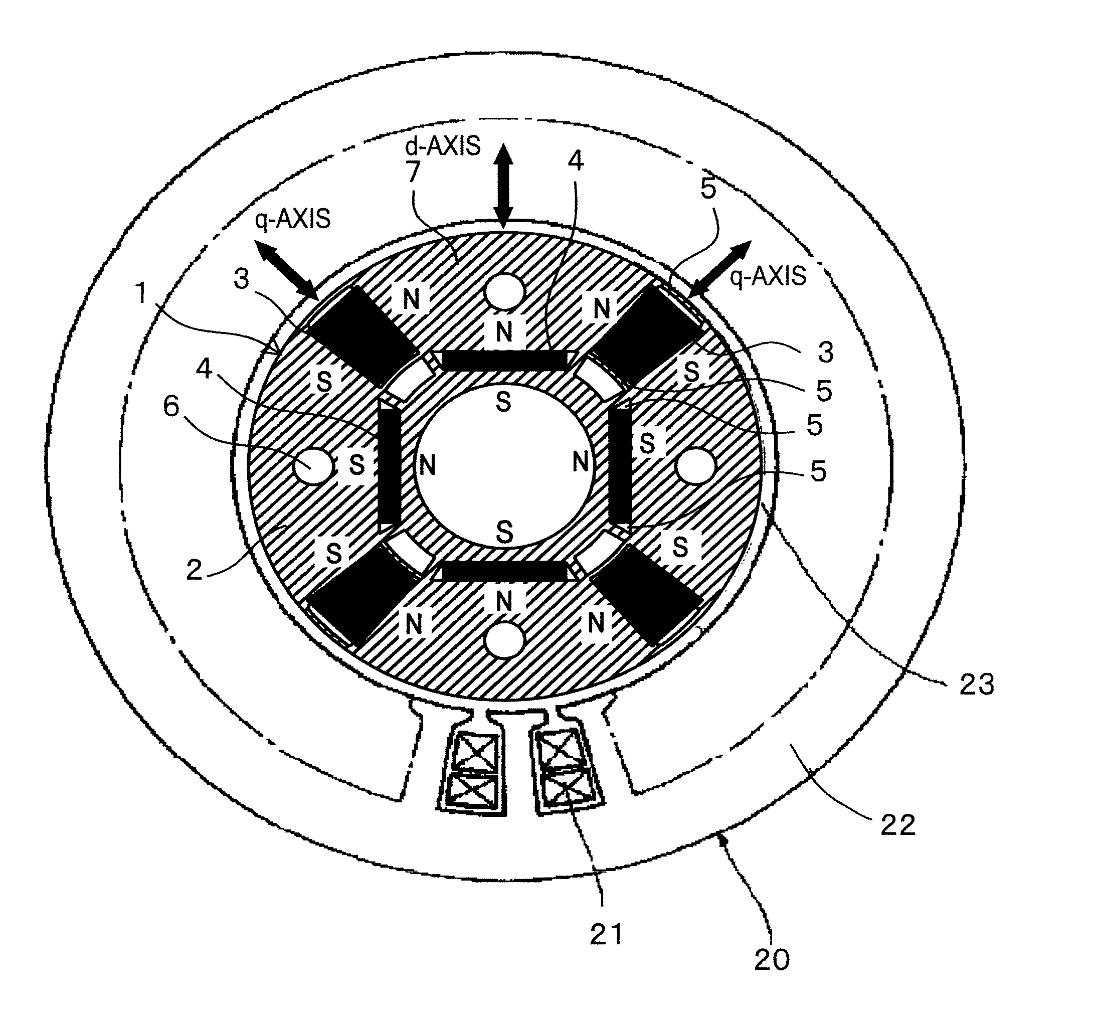
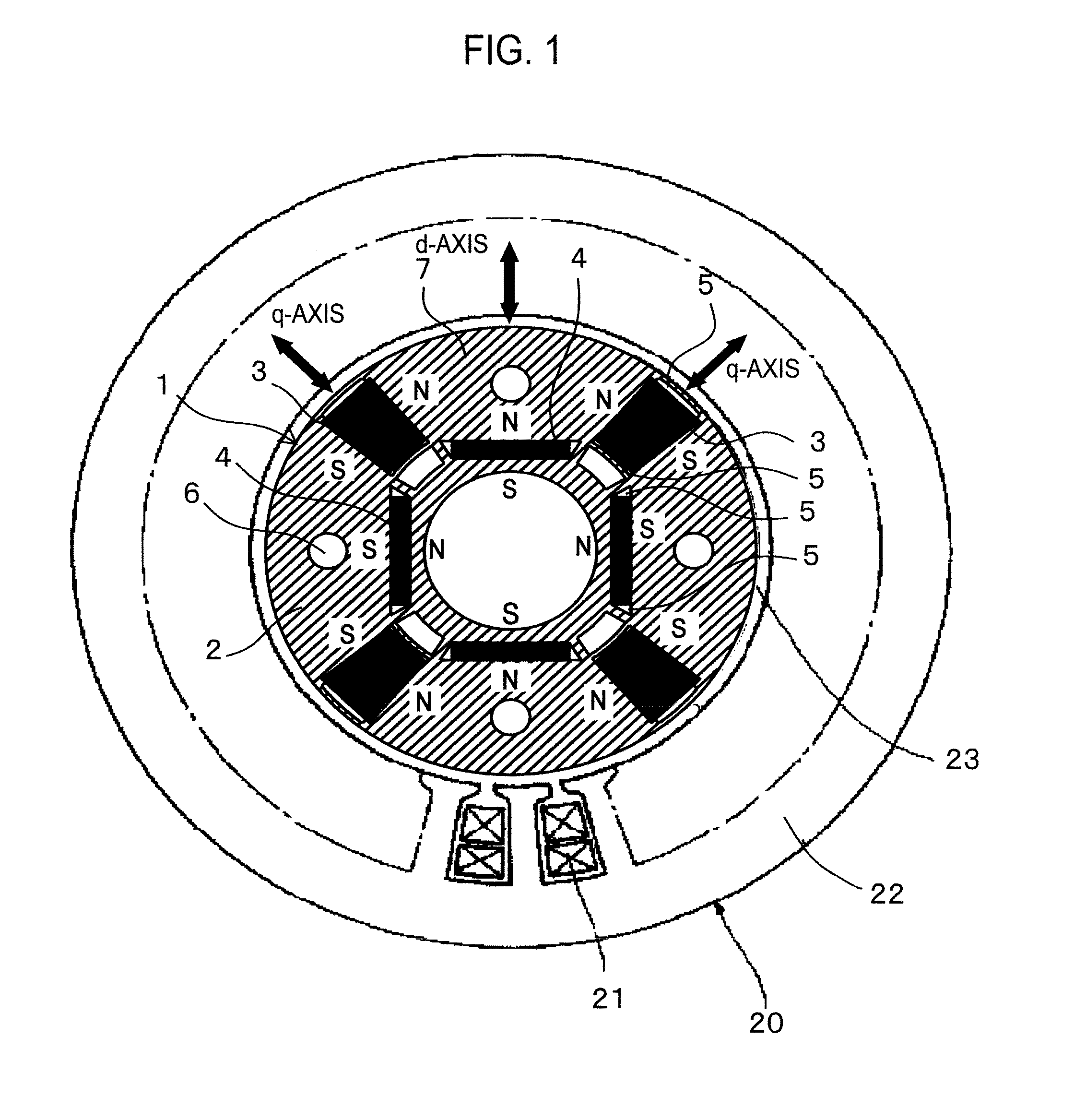
[0049]With reference to FIGS. 1 to 6, the permanent magnet rotating electrical machine according to the first embodiment of the present invention will be explained. FIG. 1 illustrates a structure of the permanent magnet rotating electrical machine according to the embodiment. Inside a stator 20, a rotor 1 is accommodated to face the stator 20 with an air gap 23 interposing between them. The stator 20 is a conventional one and is similar to that illustrated in FIG. 20.
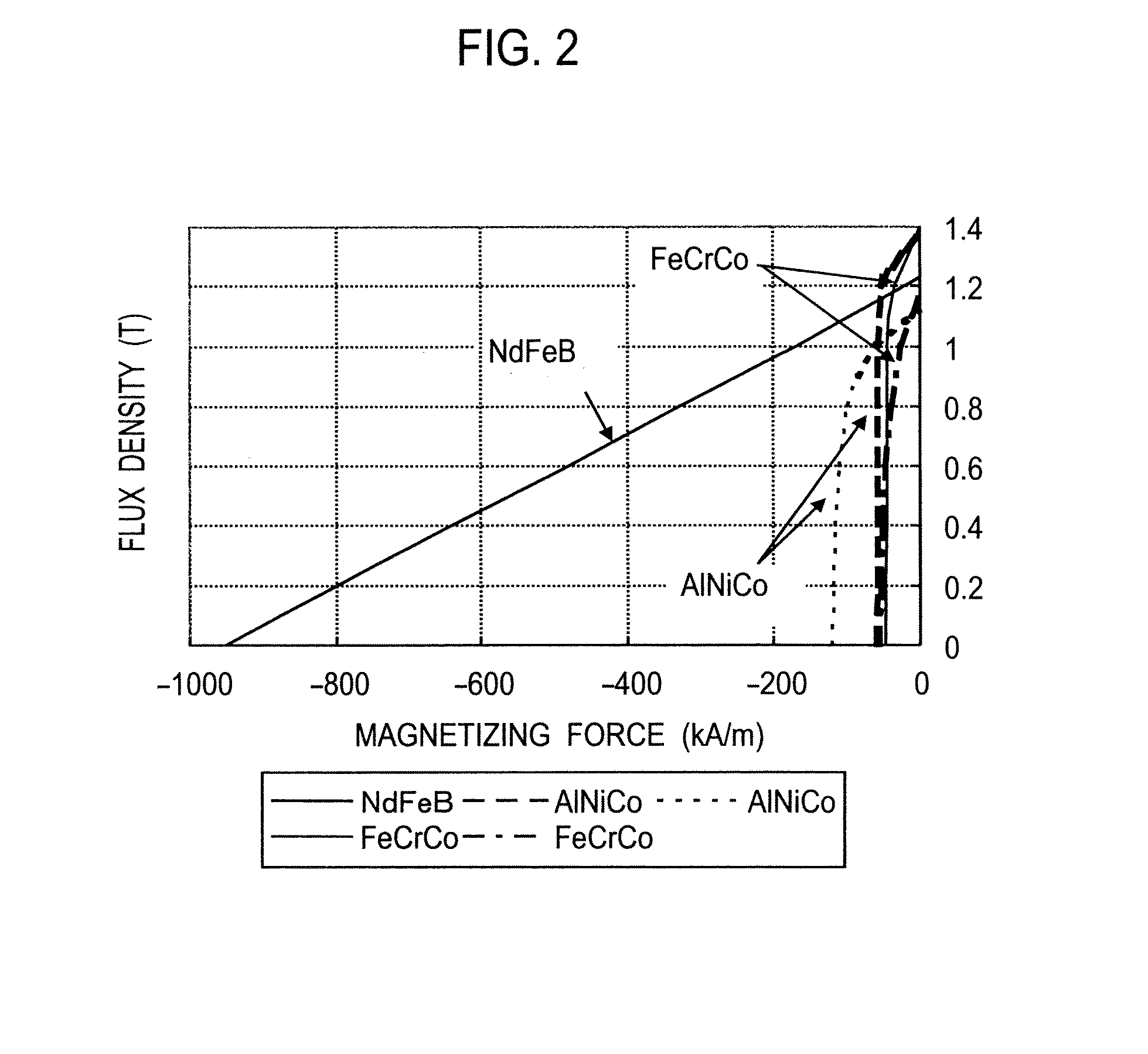
[0050]As illustrated in FIG. 1, the rotor 1 in the permanent magnet rotating electrical machine according to the embodiment includes a rotor core 2, permanent magnets 3 whose product of coercive force and thickness along magnetizing direction is small, and permanent magnets 4 whose product of coercive force and thickness along magnetizing direction is large. The rotor core 2 is constituted by laminating silicon steel plates. The permanent magnet 3 whose product of coer...
second embodiment
[0114]A permanent magnet rotating electrical machine and permanent magnet motor drive system according to the second embodiment of the present invention will be explained. This embodiment is characterized in that the permanent magnet rotating electrical machine 101 illustrated in FIG. 1 receives a pulse-like magnetic field created by a short-time d-axis current provided by the permanent magnet motor drive system illustrated in FIG. 7, to irreversibly magnetize the alnico permanent magnets 3 and change a linkage flux amount.
[0115]In this way, flux by a negative d-axis current is always created in a middle or high rotation speed zone, so that linkage flux consisting of the flux by the negative d-axis current and flux by the permanent magnets 3 and 4 is adjusted according to the flux by the negative d-axis current. Namely, in the middle or high speed zone, the pulse-like magnetic field created by a short-time d-axis current irreversibly changes the magnetized state of the alnico perman...
third embodiment
[0117]A permanent magnet rotating electrical machine according to the third embodiment of the present invention will be explained with reference to FIG. 13. The structure of a stator 20 in the permanent magnet rotating electrical machine of the embodiment is the same as that of the first embodiment illustrated in FIG. 1 and that of the related art illustrated in FIG. 20.
[0118]As illustrated in FIG. 13, a rotor 1 of this embodiment arranges each alnico permanent magnet 3 inside a rotor core 2 along a q-axis in a diametrical direction and each NdFeB permanent magnet 4 inside the rotor core 2 in a circumferential direction orthogonal to a d-axis. An inner circumferential side of the rotor core 2 of the rotor 1 is engaged with an iron shaft 9. The shaft 9 has four cut faces to form an air layer 8 between the rotor core 2 and the shaft 9. The shaft 9 may be made of a nonmagnetic material.
[0119]An armature coil 21 passes a current to generate a magnetic field for magnetizing the permanent...
PUM
| Property | Measurement | Unit |
|---|---|---|
| thickness | aaaaa | aaaaa |
| thickness | aaaaa | aaaaa |
| coercive force | aaaaa | aaaaa |
Abstract
Description
Claims
Application Information
 - R&D
- Intellectual Property
- Life Sciences
- Materials
- Tech Scout
- Unparalleled Data Quality
- Higher Quality Content
- 60% Fewer Hallucinations
Browse by: Latest US Patents, China's latest patents, Technical Efficacy Thesaurus, Application Domain, Technology Topic, Popular Technical Reports.
© 2025 PatSnap. All rights reserved.Legal|Privacy policy|Modern Slavery Act Transparency Statement|Sitemap|About US| Contact US: help@patsnap.com


