Image taking optical system

an image taking and optical system technology, applied in optics, instruments, lenses, etc., can solve the problems of difficult aberration correction of light divergence effects, too large refractive angle, and difficulty in meeting the application of compact electronic devices to the total length of the optical system, so as to improve the ability of aberration correction, reduce the total length of the image taking, and improve the effect of aberration correction

Active Publication Date: 2012-12-18
LARGAN PRECISION
View PDF10 Cites 105 Cited by
  • Summary
  • Abstract
  • Description
  • Claims
  • Application Information

AI Technical Summary

Benefits of technology

[0019]In the present invention, the aforementioned front lens group, stop, rear lens group, each lens element in the front lens group, each lens element in the rear lens group are installed with an appropriate interval apart along the optical axis to achieve a good aberration correction and a more advantageous modulation transfer function (MTF), and reduce the total length of the image taking optical system effectively to improve the aberration correction ability for applying to an optical image taking system used in compact electronic devices.
[0020]In the image taking optical system of the present invention, the meniscus front-group first lens element having a convex object side and the rear-group positive glass lens element with positive refractive power are used for image taking in an opposite direction and with a wider field angle. To overcome the shortcomings of too-large refractive angle of the rear lens group caused by the front-group first lens element to diverge light easily and poor aberration correction ability of the following lens elements, the present invention adopts a rear-group rear lens element with at least one inflection point within the rear lens group to correct the aberration and adjust the modulation transfer function (MTF), and further uses a rear-group negative lens element adjacent to the rear-group positive lens element to reduce the chromic aberration and coma aberration produced in the image taking optical system to improve the resolution of the image taking optical system, such that the aberration and distortion of the image taking optical system can meet the high resolution requirement.
[0021]Furthermore, in the image taking optical system of the present invention, the stop is a middle stop disposed between the front lens group and the rear lens group for enhancing the front stop (which is disposed between the photographed object and the first lens element), such that the exit pupil of the image taking optical system will not be too far away from the image plane For controlling the light to be incident onto the image sensor in a substantially perpendicular direction to achieve the telecentric effect, and obtain a balance between the telecentric effect and the wider field angle. With the rear-group rear lens element having at least two inflection points, the wide-angle image taking optical system has a good effect of correcting chromic aberrations caused by distortions and width.

Problems solved by technology

In the various designed five-lens image taking optical system with a constant focal length as disclosed in U.S. Pat. No. 7,710,665, can achieve a good aberration correction, but the total length of the optical system is still difficult to meet the application of the compact electronic device.
As disclosed in U.S. Pat. Nos. 7,663,813, 6,985,309, and 6,940,662 and European Pat. No. EP2012162, an optical design of the first lens element with negative refractive power is provided, but the first lens element with negative refractive power will cause a too-large refractive angle of the first lens element, and light divergence effects a difficult aberration correction to the following lens elements.
In the prior arts disclosed above, if the refractive power of the lens element installed behind the first lens element is insufficient or the aberration of the lens element nearest to the image plane is difficult to correct, then the astigmatic field curving or distortion of the image will be increased.

Method used


Image

  • Image taking optical system
  • Image taking optical system
  • Image taking optical system

Examples


first preferred embodiment

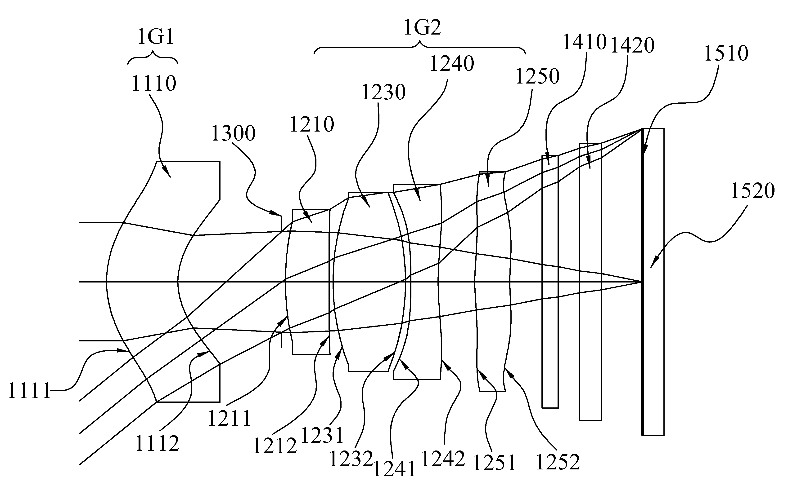
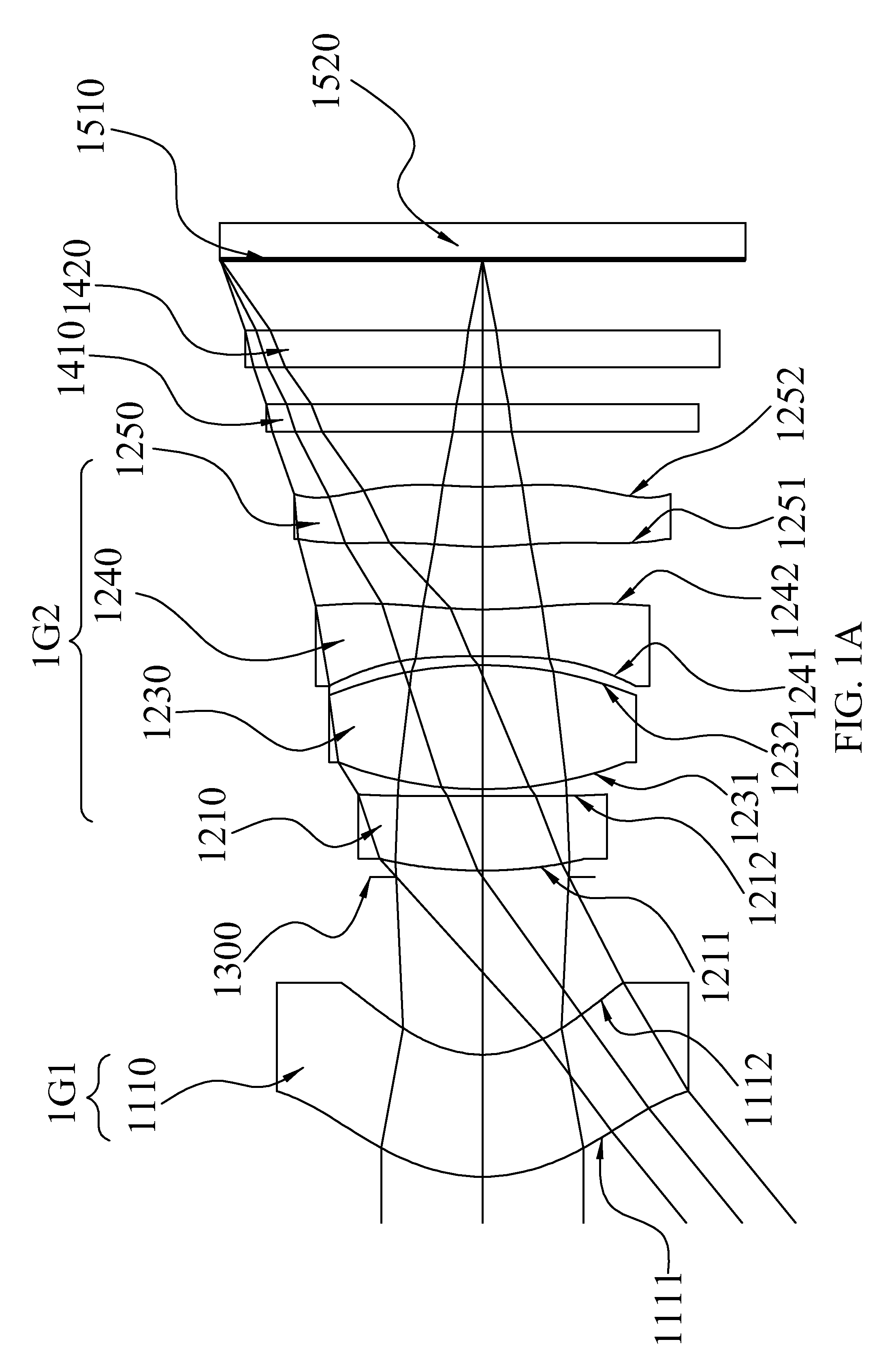
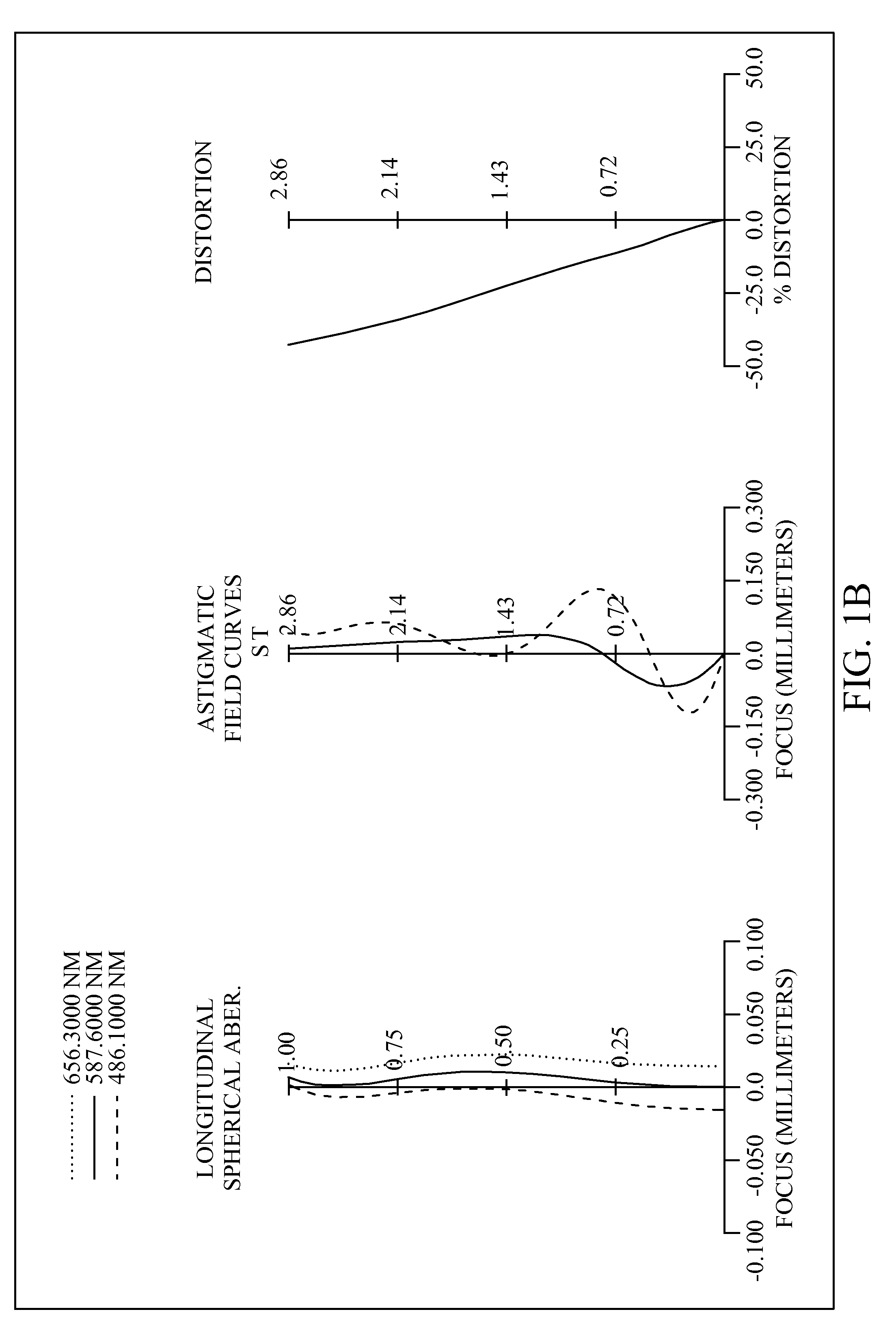
[0070]With reference to FIGS. 1A and 1B for a schematic view of an optical system and a series of aberration curves in accordance with the first preferred embodiment of the present invention respectively and Table 1 for the optical data of this preferred embodiment, the image taking optical system comprises a front lens group (1G1), a aperture stop (1300) and a rear lens group (1G2), and the aperture stop (1300) is arranged between the front lens group (1G1) and the rear lens group (1G2). The front lens group (1G1) comprises a front-group first lens element (1110) (labeled as the first lens element in Table 1), and the rear lens group (1G2) comprises four lens elements, being respectively a rear-group first lens element (1210) (labeled as the second lens element in Table 1), a rear-group positive lens element (1230) (labeled as the third lens element in Table 1), a rear-group negative lens element (1240) (labeled as the fourth lens element in Table 1) and a rear-group rear lens elem...

second preferred embodiment

[0079]With reference to FIGS. 2A and 2B for a schematic view of an optical system and a series of aberration curves in accordance with the second preferred embodiment of the present invention respectively and Table 4 for the optical data of this preferred embodiment, the image taking optical system comprises a front lens group (2G1), a aperture stop (2300) and a rear lens group (2G2), and the aperture stop (2300) is arranged between the front lens group (2G1) and the rear lens group (2G2). The front lens group (2G1) comprises a front-group first lens element (2110) (labeled as the first lens element in Table 4), and the rear lens group (2G2) comprises four lens elements, being respectively a rear-group first lens element (2210) (labeled as the second lens element in Table 4), a rear-group positive lens element (2230) (labeled as the third lens element in Table 4), a rear-group negative lens element (2240) (labeled as the fourth lens element in Table 4) and a rear-group rear lens ele...

third preferred embodiment

[0089]With reference to FIGS. 3A and 3B for a schematic view of an optical system and a series of aberration curves in accordance with the third preferred embodiment of the present invention respectively and Table 7 for the optical data of this preferred embodiment, the image taking optical system comprises a front lens group (3G1), a aperture stop (3300) and a rear lens group (3G2), and the aperture stop (3300) is arranged between the front lens group (3G1) and the rear lens group (3G2). The front lens group (3G1) comprises a front-group first lens element (3110) (labeled as the first lens element in Table 7) and a front-group second lens element (3120) (labeled as the second lens element in Table 7). The rear lens group (3G2) comprises three lens elements, being respectively a rear-group positive lens element (3230) (labeled as the third lens element in Table 7), a rear-group negative lens element (3240) (labeled as the fourth lens element in Table 7) and a rear-group rear lens el...


PUM


Abstract

An image taking optical system, sequentially arranged from an object side to an image side along an optical axis comprising: a front lens group, a stop and a rear lens group. The front lens group comprises at least a meniscus front-group first lens element with a convex object-side surface. The rear lens group comprises at least three lens elements. Through the means of field adjustments that result in desirable distorted images, the image taking optical system may shorten the total length while enhancing the ability to create a larger field of view for panorama usages in compact cameras and mobile phones.

Description

BACKGROUND OF THE INVENTION[0001]1. Field of the Invention[0002]The present invention relates to an image taking optical system, and more particularly to an image taking optical system comprising two lens groups to provide good aberration compensation and short total length in order to be applied to electronic products.[0003]2. Description of the Related Art[0004]At present, optical systems used for digital cameras or lenses used for web cameras or mobile phones tend to provide a larger field angle, a good aberration correction ability and high image quality as user's requirements besides a compact design and a low cost.[0005]In general, a conventional image taking optical system of a mini electronic product comes with different designs, including the two-lens, three-lens, four-lens, and five-or-more lens designs. If the image quality is taken into consideration, the image taking optical system for the compact digital cameras, web cameras, and mobile phone cameras requires a compact...

Claims


Application Information

Patent Timeline
Patent Type & Authority Patents(United States)
IPC IPC(8): G02B13/04G02B13/18
CPCG02B13/006G02B13/0045
Inventor HUANG, HSIN-HSUAN
Owner LARGAN PRECISION
Why Eureka
Try Eureka