One cycle control method for power factor correction

a power factor and control method technology, applied in process and machine control, electric variable regulation, instruments, etc., can solve the problems of high component count, high cost, complicated design of pfc circuit, etc., and achieve the effect of realizing the one-cycle control strategy efficiently

Active Publication Date: 2012-12-18
GREE ELECTRIC APPLIANCES INC
View PDF14 Cites 13 Cited by
  • Summary
  • Abstract
  • Description
  • Claims
  • Application Information

AI Technical Summary

Benefits of technology

[0005]The present invention aims at providing a one cycle control method for power factor correction , which can be integrated into the main control chip of system by software, so as to realize the one cycle control strategy efficiently by cooperating with a simple boost circuit.
[0017]The advantages of the present invention over the prior art are as follows: the function of power factor correction can be implemented by integrating the software of the method into the main control chip (DSP, for example) of system and cooperating with the simple boost circuit, without using the traditional circuit for power factor correction and the specific one cycle control chip for PFC, which reduces the cost of the system; more especially, the present invention avoids sampling around the switching instant by calculating the sampling triggering instant, which ensures the sampling data true and correct, further ensures the optimal effect of

Problems solved by technology

However, the traditional PFC circuit has complicated techniques and design, and high component count, which makes it large in size and high in cost.
So the design of the PFC circuit often makes a compromise between performance and cost.
Although one cycle control chips for PFC are simple and reliable, the cost-to-use is too high.
DSP and other main control chips have powerful capacity of software integration, compatibility and signal processing, so it will be an increase of cost and a waste of resources as well if a specific one cycle control chip for PFC is additionally applied in such system.

Method used


Image

  • One cycle control method for power factor correction
  • One cycle control method for power factor correction
  • One cycle control method for power factor correction

Examples


Embodiment Construction

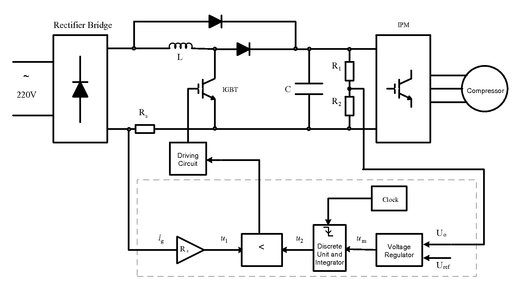
[0025]As shown in FIG. 1, the method according to the present invention is based on the boost circuit and the main control chip of system. The boost circuit is an accustomed circuit which comprises an AC input, a rectifying circuit, an inductor, fast recovery diodes, a capacitor, a DC output, an inductive current sampling circuit, an output voltage sampling circuit, a switch transistor (IBGT or MOSFET) and a driving circuit of the switch transistor. The part outlined in a dashed frame is a control module corresponding to the method of the present invention, which is integrated in the main control chip.

[0026]The principle of the one cycle control method for PFC will be described with reference to FIG. 1. The one cycle control for PFC aims at getting the inductive current follow the wave of the input rectified voltage ug and ensuring the output voltage Uo, to be stabilized at the given value. If the inductive current is proportional to the input voltage and has the same phase as the i...


PUM


Abstract

A one cycle control method for power factor correction based on a boost circuit and a main control chip of system comprises the steps of: (1) Determining whether soft-start ends or not; if the soft-start ends, processing step (2) directly, if not, increasing reference value Uref of output voltage and then processing step (2); (2) Reading sampling output voltage Uo, and sampling inductive current ig according to A / D sampling triggering instant; (3) Calculating duty ratio of PWM signal for driving the switch transistor; (4) Outputting PWM signal; (5) Calculating the next A / D sampling triggering instant according to the duty ratio of PWM signal; (6) Returning to step (2). The present invention can implement the function of power factor correction by integrating the software of the method into the main control chip of the existing system and cooperating with the simple boost circuit, without using the traditional circuit for power factor correction and the specific one cycle control chip for PFC, which reduces the cost of the system. Also the present invention ensures the sampling data true and correct, and the stable operation of system, by simple processing of the sampling triggering instant.

Description

TECHNICAL FIELD[0001]The present invention relates to power supply techniques, more particularly, to a one cycle control method for power factor correction based on a boost circuit.BACKGROUND OF THE INVENTION[0002]A Power Factor Correction (PFC) circuit is used for reducing the input harmonic current. However, the traditional PFC circuit has complicated techniques and design, and high component count, which makes it large in size and high in cost. So the design of the PFC circuit often makes a compromise between performance and cost.[0003]In recent years, the studies of the one cycle control method for PFC focus on how to simplify the structure of the traditional control circuit for PFC, so as to avoid sampling the input voltage and eliminate the complicated analog multiplier. While the one cycle control circuit for PFC solves these problems very well. So far, one cycle control chips for PFC have been developed and applied, such as the one cycle control continuous conduction mode PF...

Claims


Application Information

Patent Timeline
Patent Type & Authority Patents(United States)
IPC IPC(8): H02M5/42G05F1/70
CPCH02M1/4225Y02B70/126Y02B70/10G05F1/70H02M1/42
Inventor MI, XUETAOGUO, QINGFENGXU, MIN
Owner GREE ELECTRIC APPLIANCES INC
Why Eureka
Try Eureka