Electric power steering apparatus
- Summary
- Abstract
- Description
- Claims
- Application Information
AI Technical Summary
Benefits of technology
Problems solved by technology
Method used
Image
Examples
first embodiment
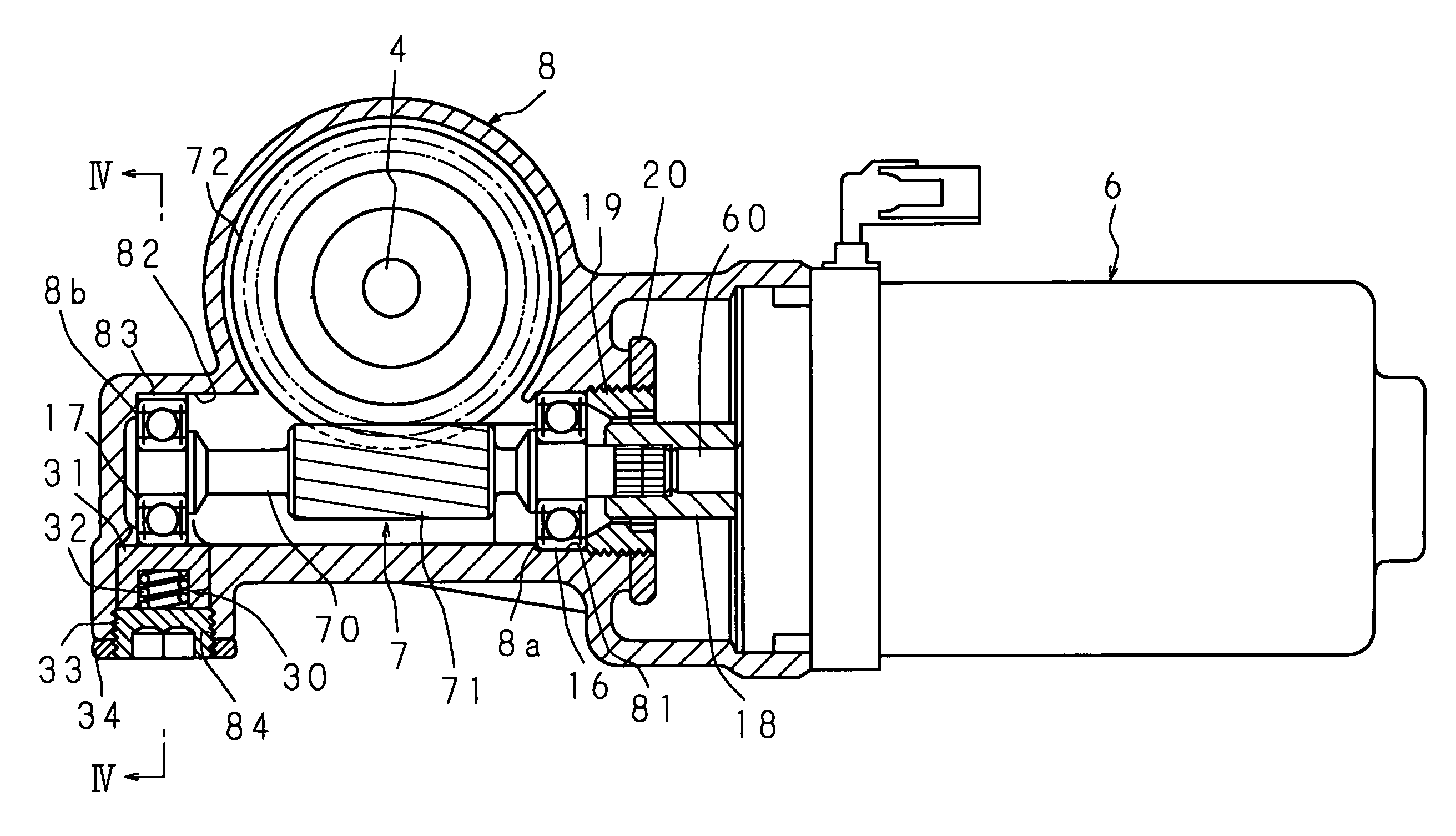
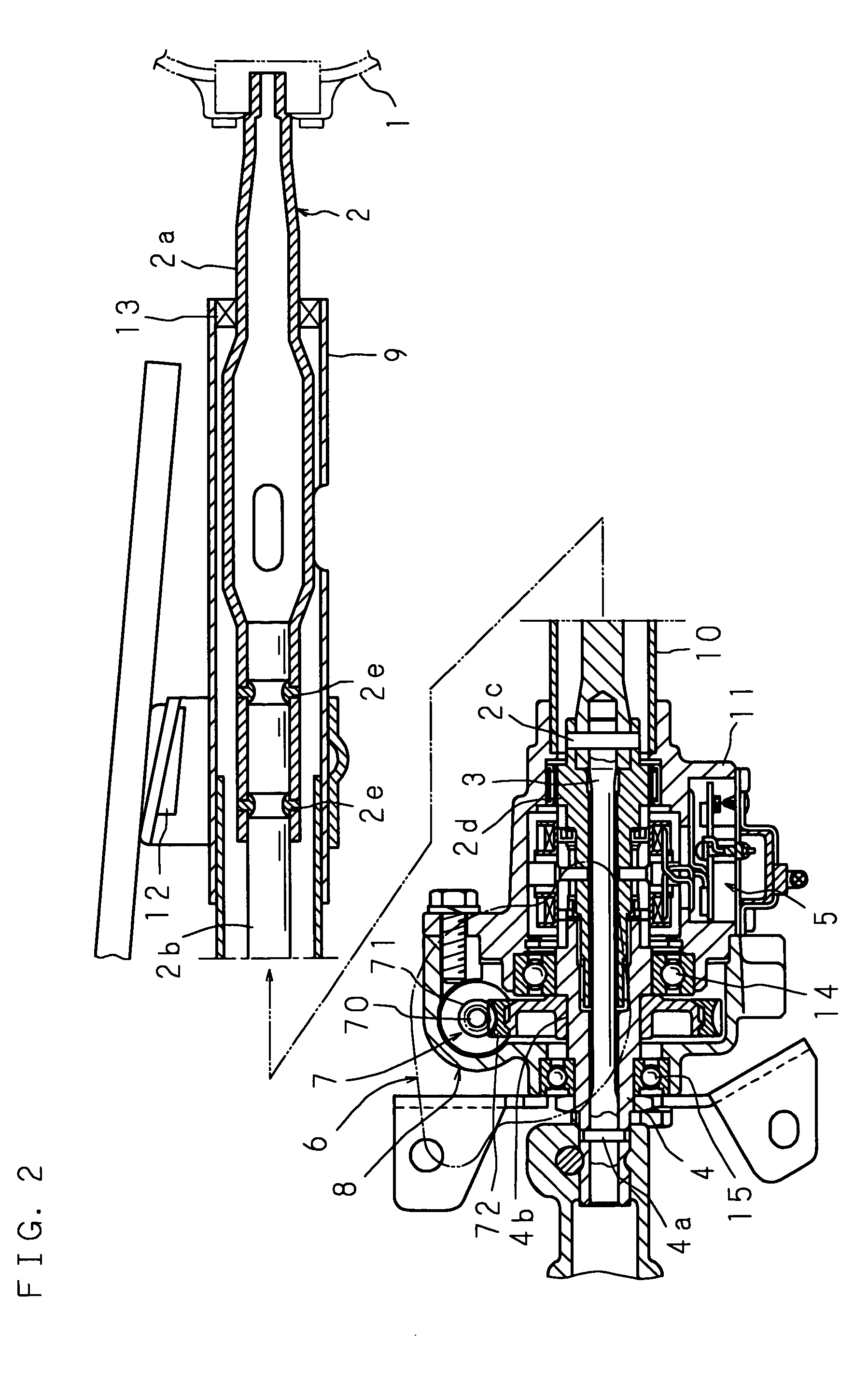
[0028]FIG. 2 is a sectional view of the whole of an electric power steering apparatus relating to the present invention. The electric power steering apparatus, as shown in FIG. 2, includes: a first steering shaft 2 connected to a steering wheel 1; a torque sensor 5 sensing a steering torque by a relative rotary displacement of a second steering shaft 4 to the first steering shaft 2, the second steering shaft 4 being coupled with the first steering shaft 2 via a torsion bar 3; a constant velocity joint transmitting a rotary motion of the second steering shaft 4 to a steering mechanism; a reduction mechanism 7 having a worm 71 and a worm wheel 72, which reduces a rotary motion of an electric motor 6 for steering assistance driven based on a sense result of the torque sensor 5 and transmits the reduced rotary motion to the second steering shaft 4; a first shaft housing 9 and a second shaft housing 10 to enclose and support the first steering shaft 2; a sensor housing 11 accommodating t...
second embodiment
[0040]FIG. 5 is a sectional view of the reduction mechanism and the electric motor combined in a second embodiment and FIG. 6 is a sectional view taken on line of VI to VI of FIG. 5. The electric power steering apparatus of the second embodiment has a structure in which comparing with the first embodiment, neither of the spring body 32 and the spring supporter 31 of the above-mentioned biasing member 30 is present, a screw body 35 is screwed in a tapped hole 84 of the gear housing 8, the screw body 35 being put in contact with the outer circumferential surface of the second bearing 17; the second bearing 17 is deflected toward the concave portion 83 by operating the screw body 35 and further, no first regulatory portion 8a is present. The other parts of the structure and workings thereof are the same as those in the first embodiment, and therefore the same reference marks are attached to parts in common use with both embodiments and descriptions thereof are omitted.
[0041]In the seco...
third embodiment
[0043]FIG. 7 is a sectional view of the reduction mechanism and the electric motor combined in a third embodiment. The electric power steering apparatus of the third embodiment has a structure in which comparing with the first embodiment, the first bearing 16 is deflectable instead of the second bearing 17, the biasing member 30 biasing the first bearing 16 is provided and furthermore the output shaft 60 and the worm shaft 70 are coupled by a constant velocity joint 21 with neither of the screw body 19 and the lock nut 20. The other parts of the structure and workings thereof are the same as those in the first embodiment, and therefore the same reference marks are attached to parts in common use with both embodiments and descriptions thereof are omitted.
[0044]The constant velocity joint 21 is coupled with the output shaft 60 and the worm shaft 70, respectively, via yokes 21b and 21b, and joint crosses 21c and 21c provided at the both end portions of a shaft body 21a to transmit a ro...
PUM
 Abstract
Description
Claims
Application Information
 - R&D
- Intellectual Property
- Life Sciences
- Materials
- Tech Scout
- Unparalleled Data Quality
- Higher Quality Content
- 60% Fewer Hallucinations
Browse by: Latest US Patents, China's latest patents, Technical Efficacy Thesaurus, Application Domain, Technology Topic, Popular Technical Reports.
© 2025 PatSnap. All rights reserved.Legal|Privacy policy|Modern Slavery Act Transparency Statement|Sitemap|About US| Contact US: help@patsnap.com


