
Centrifugal separation-use device

a centrifugal separation and container technology, applied in the direction of centrifuges, laboratory glassware, liquid displacement, etc., can solve the problems of high risk, increased risk of infection in operation, and torn sterilized bags, etc., and achieves easy maintenance of centrifugal separation-use containers in a clean state and low cost

Inactive Publication Date: 2012-12-25
KYOCERA MEDICAL CORP
View PDF7 Cites 0 Cited by
  • Summary
  • Abstract
  • Description
  • Claims
  • Application Information

AI Technical Summary

Benefits of technology

[0013]Accordingly; in order to solve the technical problems described above, the present invention is intended to provide a centrifugal separation-use device capable of maintaining a centrifugal separation-use container in a clean state easily at low cost even when centrifugal separation treatment is carried out using a centrifugal separator in an unclean field.
[0022]Since the outer container is subjected to large centrifugal force during centrifugal separation treatment, the outer container is required to be configured so as not to be deformed or broken by the centrifugal force. Although it is effective to increase the thickness of the side wall of the outer container in order to prevent deformation and breakage, this results in increasing the size of the outer container. It is thus preferable that the outer container is made of a self-shape retaining material so as not to be deformed by centrifugal force.

Problems solved by technology

However, when an attempt is made to carry out collection using the above-mentioned method, all the devices are required to be used while being set in a centrifugal separator.
Hence, the assistant in the unclean field and the outside-air side of the device in the unclean field become close to the affected area of a patient and may increase the risk of infection in an operation in which a material is embedded.
However, since the sterilized bag is insufficient in strength, there is a problem of having a high risk that the sterilized bag is torn when centrifugal separation treatment is carried out.
Furthermore, although it is also conceivable to use a method for sterilizing the rotor of a centrifugal separator, there is a problem of imposing quite a burden when the rotor of a large-size centrifugal separator is sterilized for each operation.
Moreover, although it is further conceivable to use a method for automatically carrying out centrifugal separation treatment under a sterile environment using an automated centrifugal separator or the like, there is a problem of the very high cost of the centrifugal separator.

Method used


Image

  • Centrifugal separation-use device
  • Centrifugal separation-use device
  • Centrifugal separation-use device

Examples


Embodiment Construction

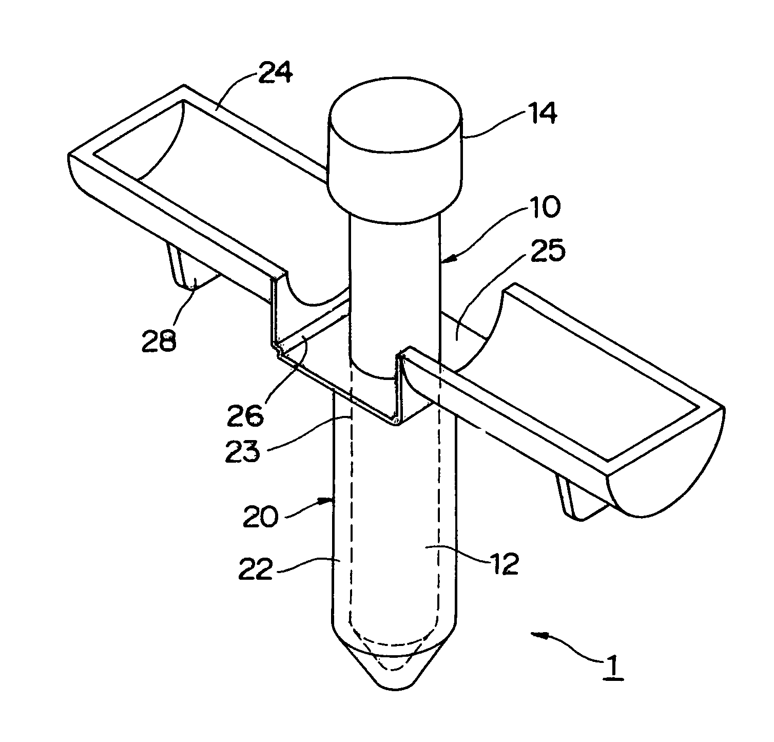
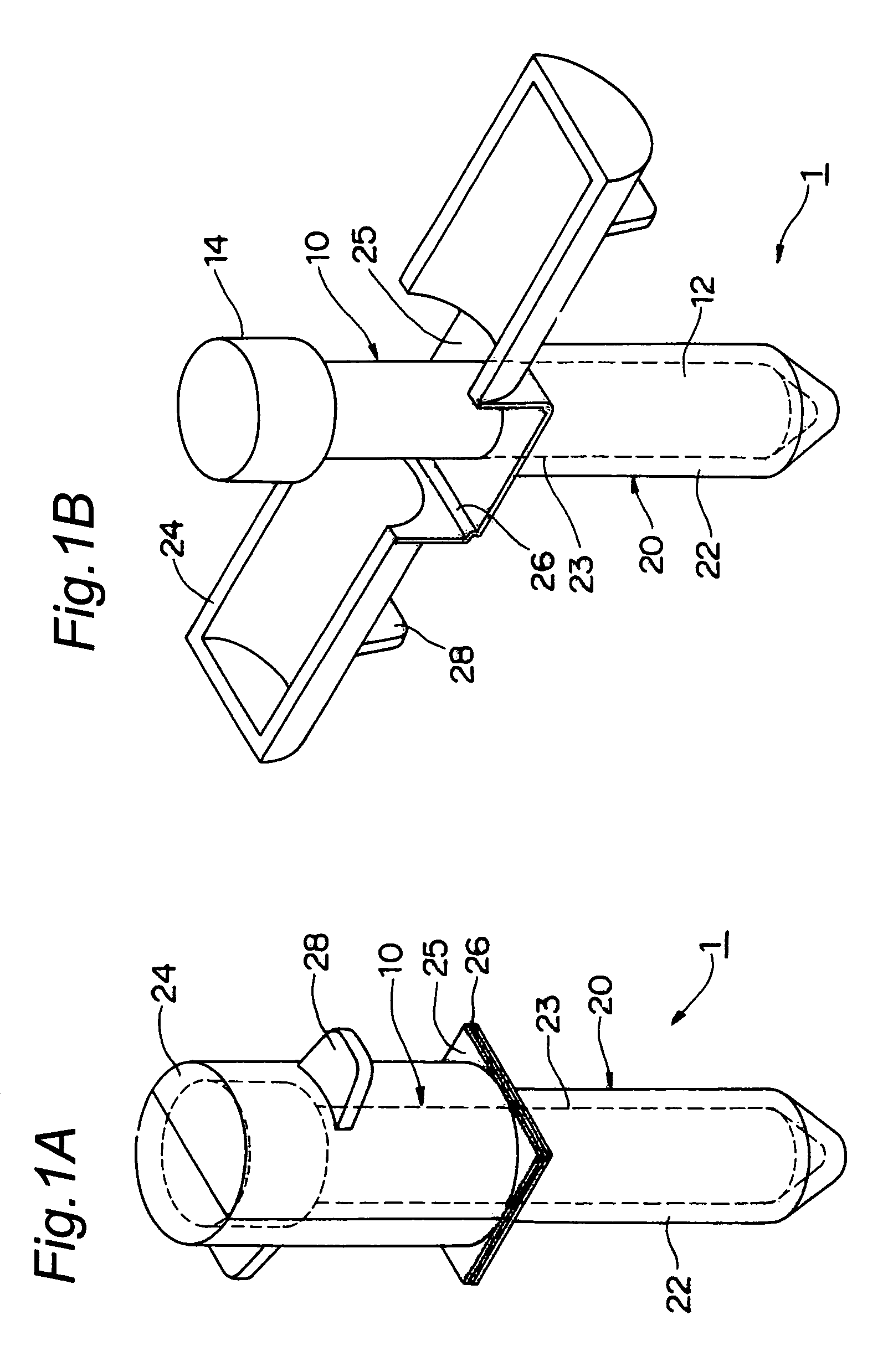
[0032]A first embodiment of a centrifugal separation-use device 1 according to the present invention will be described below in detail referring to FIGS. 1A and 1B to 5.

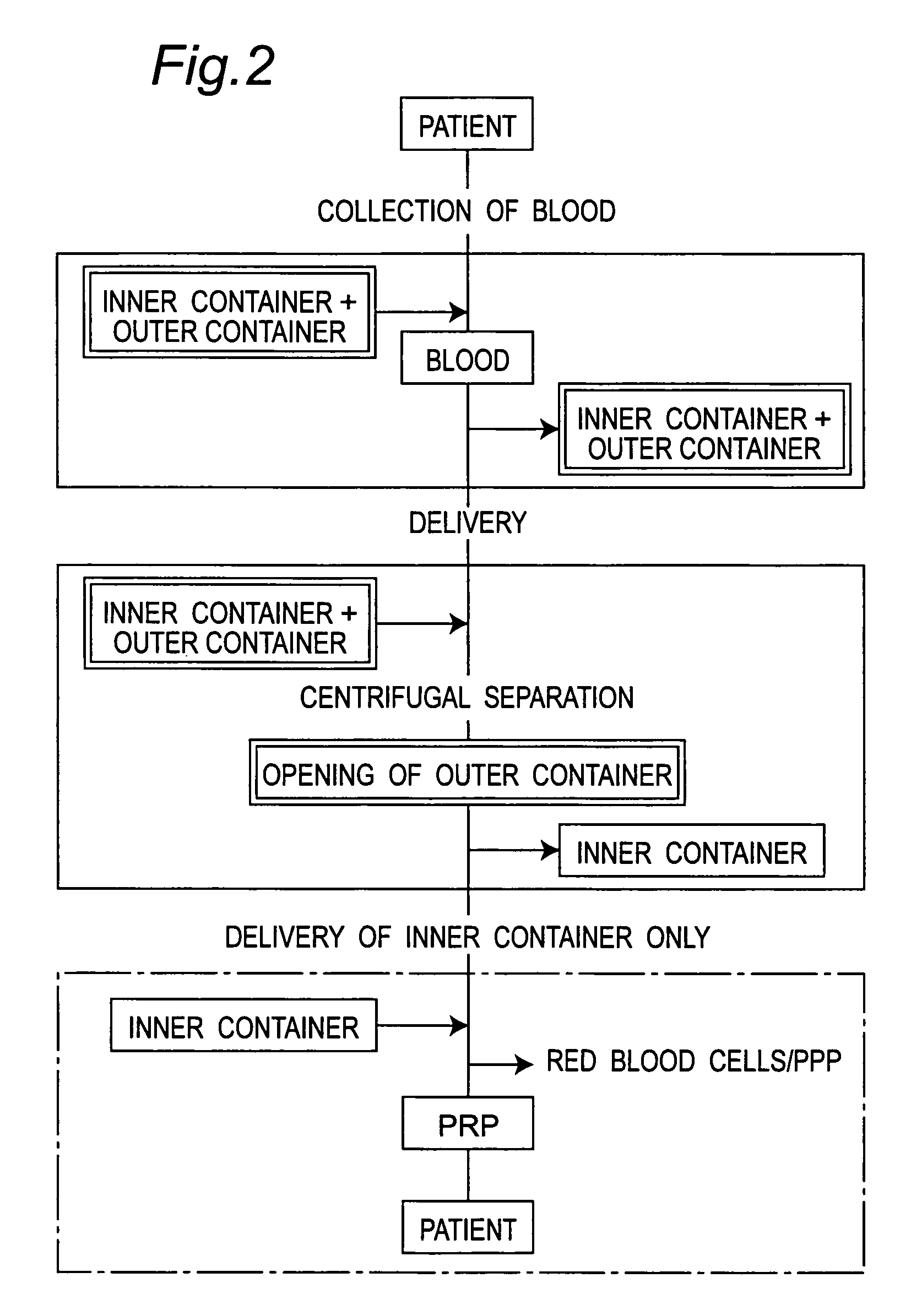
[0033]FIGS. 1A and 1B are perspective views schematically showing the centrifugal separation-use device 1 according to the first embodiment of the present invention. FIG. 1A shows a state where a door section 24 is closed, and FIG. 1B shows a state where the door section 24 is open. FIG. 2 is a flowchart showing a centrifugal separation process performed when the centrifugal separation-use device 1 according to the present invention is used to collect platelet-rich plasma from blood. FIG. 3 is a flowchart showing another centrifugal separation process performed when the centrifugal separation-use device 1 according to the present invention is used to collect platelet-rich plasma from blood. FIG. 4 is a view schematically illustrating the centrifugal separation process shown in FIG. 3. FIG. 5 is a flowchart showing st...


PUM

PropertyMeasurementUnit
lengthaaaaaaaaaa
centrifugal forceaaaaaaaaaa
concentrationsaaaaaaaaaa

Abstract

The present invention provides a centrifugal separation-use device capable of maintaining a centrifugal separation-use container in a clean state easily at low cost even when centrifugal separation treatment is carried out using a centrifugal separator in an unclean field. A centrifugal separation-use device 1 for collecting a target component by subjecting a solution containing multiple components to centrifugal separation treatment comprises an inner container 10 having a cylindrical section 12 for accommodating the solution and a plug 14 for hermetically sealing the cylindrical section and configured so as to accommodate the solution in a hermetically sealed state, and an outer container 20 having a support section 22 for removably accommodating the cylindrical section and a delivery section 24 for exposing part of the inner container so that the inner container can be removed, and configured so as to accommodate the inner container in a hermetically sealed state.

Description

BACKGROUND[0001]1. Field of this Invention[0002]The present invention relates to a centrifugal separation-use device for collecting a target component from a liquid, such as blood, containing multiple components by centrifugal separation treatment while its inner container is maintained in a sterilized state.[0003]2. Description of the Prior Art[0004]The blood subjected to centrifugal separation treatment after addition of an anticoagulant is largely separated into three layers, a red blood cell layer, a white blood cell layer and a plasma layer. Since the components contained in the respective separated layers are very useful for living tissue, they are used for various medical treatment methods.[0005]It is known that the platelets contained in the plasma layer release various cytokines including platelet-derived growth factor (PDGF) due to degranulation in the process of a blood coagulation reaction. For this reason, it is attempted to use plasma (platelet-rich plasma: PRP) contai...

Claims


Application Information

Patent Timeline
Patent Type & Authority Patents(United States)
IPC IPC(8): B01D21/26
CPCA61M1/3693B01L3/5021B01L9/06B04B5/0414Y10T436/25375B01L2200/14B04B2005/0435B01L2200/025A61M2202/10
Inventor SHINTANI, NORIYUKINOSAKA, SHUJIYOKOKAWA, MICHIHIRO
Owner KYOCERA MEDICAL CORP
Learn More